
Laser distance measuring system

A technology of laser distance measurement and laser transmitter, which is applied in radio wave measurement systems, measurement devices, electromagnetic wave reradiation, etc., and can solve problems such as complex optical system, mechanical structure and circuit composition, poor stability and reliability, and complex circuits , to achieve the effect of convenient and intuitive reading, high accuracy and small size

Inactive Publication Date: 2008-07-09
薛志强
View PDF0 Cites 66 Cited by
  • Summary
  • Abstract
  • Description
  • Claims
  • Application Information

AI Technical Summary

Problems solved by technology

The time difference calculation method used in the current pulse-echo (TOF) laser ranging method has the disadvantages of complex circuit, high cost, low accuracy, low resolution, poor stability and reliability.
Most products using pulse-echo laser ranging methods have the disadvantages of relatively complex optical systems, mechanical structures, and circuit components.

Method used


Image

  • Laser distance measuring system
  • Laser distance measuring system
  • Laser distance measuring system

Examples


Embodiment Construction

[0020] The present invention will be described in detail below in conjunction with specific embodiments.

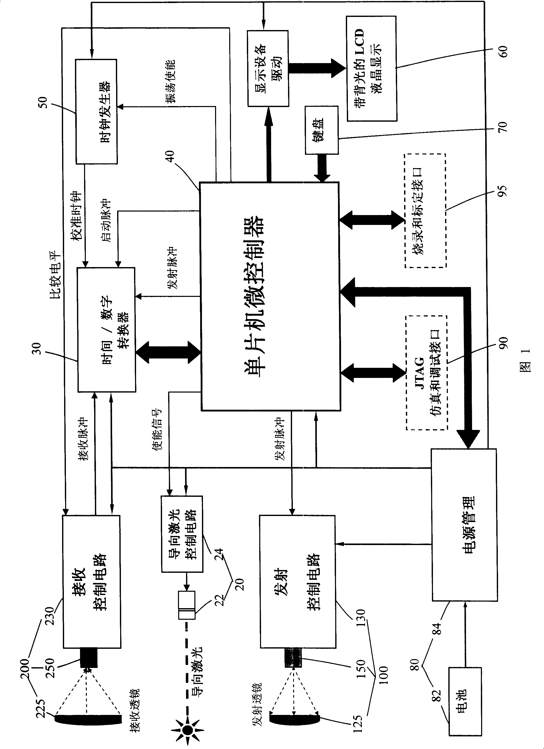
[0021] Please refer to FIG. 1 . FIG. 1 is a schematic diagram of an overall module of the laser ranging system of the present invention. The laser ranging system of the present invention comprises: a transmitting module 100, a receiving module 200, a guiding laser module 20, a time / digital converter (TDC, Time-to-Digital Converter) 30, a single-chip microcontroller (Single Chip Microcontroller) 40, a clock Generator 50 , LCD liquid crystal display device 60 with backlight, keyboard 70 , power supply unit 80 , JTAG (Joint Test Action Group, boundary scan test standard) emulation and debugging interface 90 , and programming and calibration interface 95 .

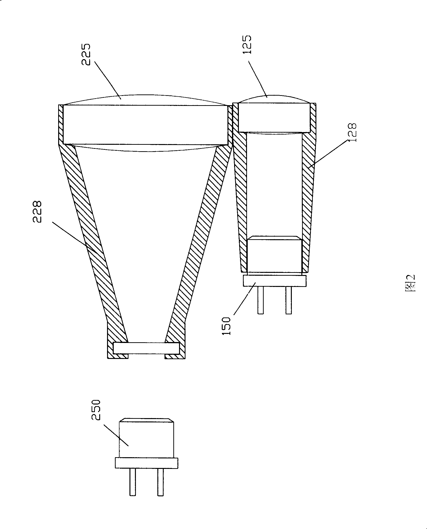
[0022] Please refer to Fig. 1 and Fig. 2 together, this emission module 100 further comprises: the emission optical system that is formed by emission lens 125 and the emission cavity 128 that installs this emission lens 1...


PUM


Abstract

The invention relates to a laser ranging system, which comprises a transmitting module comprising a transmitting optical system and a laser emitter for emitting a pulsed laser signal; a receiving module comprising a receiving optical system and a laser receiver for receiving the pulsed laser signal and converting the pulsed laser signal to a pulsed electrical signal; a time / digital converter for detecting and calculating the time difference between the transmitting the pulse signal and the receiving the pulse signal; a clock generator for outputting a calibrated clock signal to the time / digital converter; and a single chip microcontroller for controlling the transmitting module, the receiving module, the time / digital converter and the clock generator and calculating the actual distance of a target object from the position of the laser ranging system according to the time difference. The inventive laser ranging system has the advantages of compact optical system, high accuracy in time difference detection, calculation and calibration, small size of the entire product, low cost, less error and high reliability.

Description

【Technical field】 [0001] The invention relates to a laser ranging system, in particular to a laser ranging system adopting a pulse-echo (TOF, Time-of-Flight) laser ranging method. 【Background technique】 [0002] At present, there are many types of laser range finders, and there are many principles of using laser range finders. At present, the principles used in laser ranging can be roughly divided into three types: interference type, phase type and pulse echo type: [0003] 1. Interferometric laser ranging. The interferometric laser ranging method is extremely sensitive to the vibration of the external environment, and can only measure relative displacement, so it is suitable for precise measurement of extremely short distances and stable external environments. [0004] Second, phase laser ranging. The resolution of the phase laser ranging method is high, but since the phase detector can only measure the phase difference between the two signals (transmitting and receiving...

Claims


Application Information

Patent Timeline
Patent Type & Authority Applications(China)
IPC IPC(8): G01S17/08G01S17/10
Inventor 薛志强
Owner 薛志强
Learn More