Display device and method of driving thereof

a display device and display technology, applied in static indicating devices, instruments, non-linear optics, etc., can solve problems such as false contours, and achieve the effects of reducing false contour noise, good display performance, and increasing electric power consumption

Inactive Publication Date: 2007-10-16
SEMICON ENERGY LAB CO LTD
View PDF58 Cites 25 Cited by
  • Summary
  • Abstract
  • Description
  • Claims
  • Application Information

AI Technical Summary

Benefits of technology

[0015]The present invention has been made in view of the aforementioned problems, and an object of the present invention is to provide a display device that achieves good display performance without an increase in electric power consumption and with big lowering of false contour noise, and in addition, to provide a method of driving the display device.

Problems solved by technology

It has been found that the cause of false contours is that portions in which light emission or non-light emission are continuous, exist over a wide range capable of being recognized by the resolution of human eyes.

Method used


Image

  • Display device and method of driving thereof
  • Display device and method of driving thereof
  • Display device and method of driving thereof

Examples


embodiment mode 1

[0079]Embodiment Mode 1 of the present invention is explained below. Note that the display device of the present invention, and the method of driving the display device of the present invention, are not limited to the example shown below. Embodiment Mode 1 shows the case where the order of appearance of subframe periods differs between the odd number lines of pixels connected to the gate signal line of odd number line and the even number lines of pixels connected to the gate signal line of the even number line.

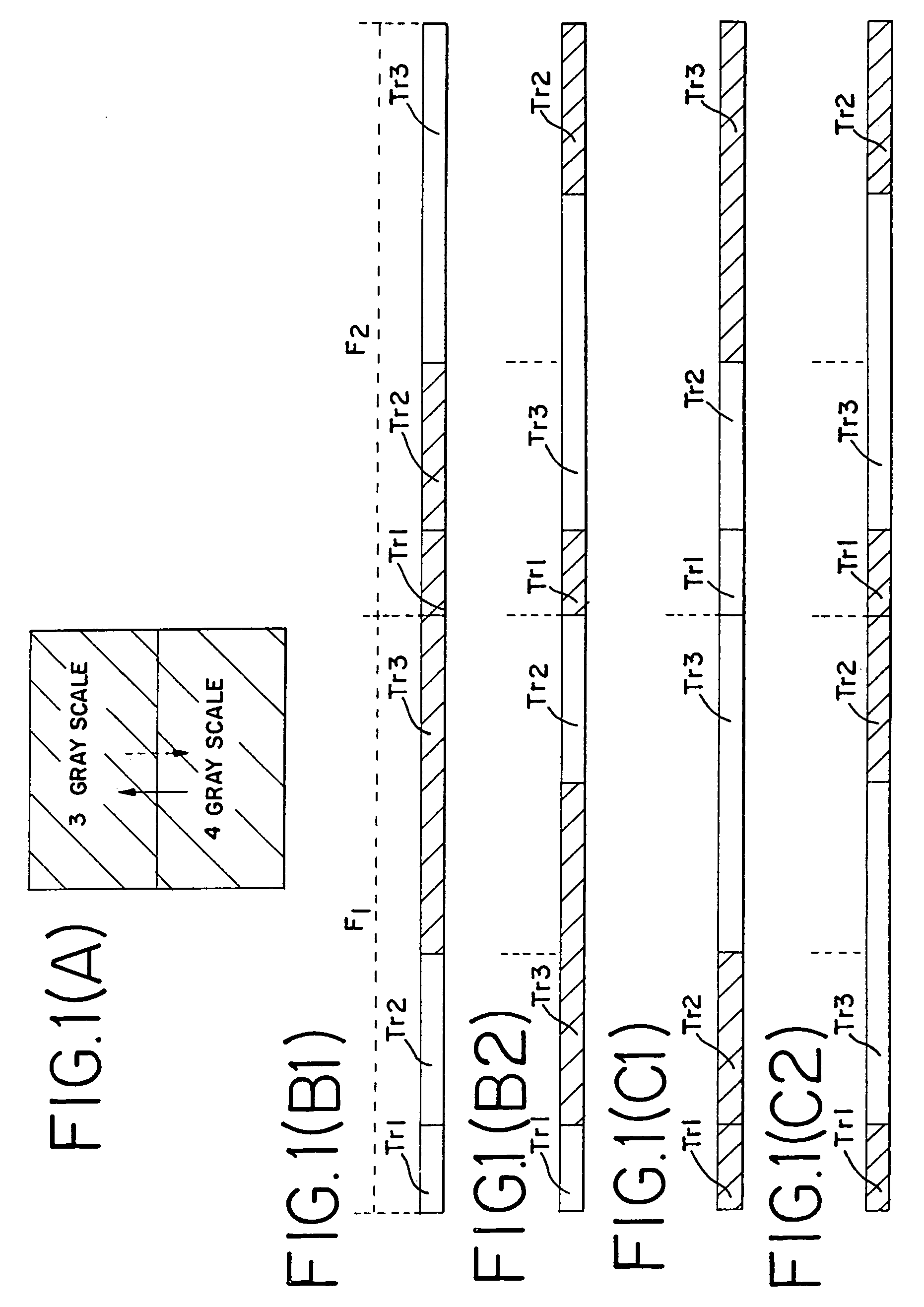
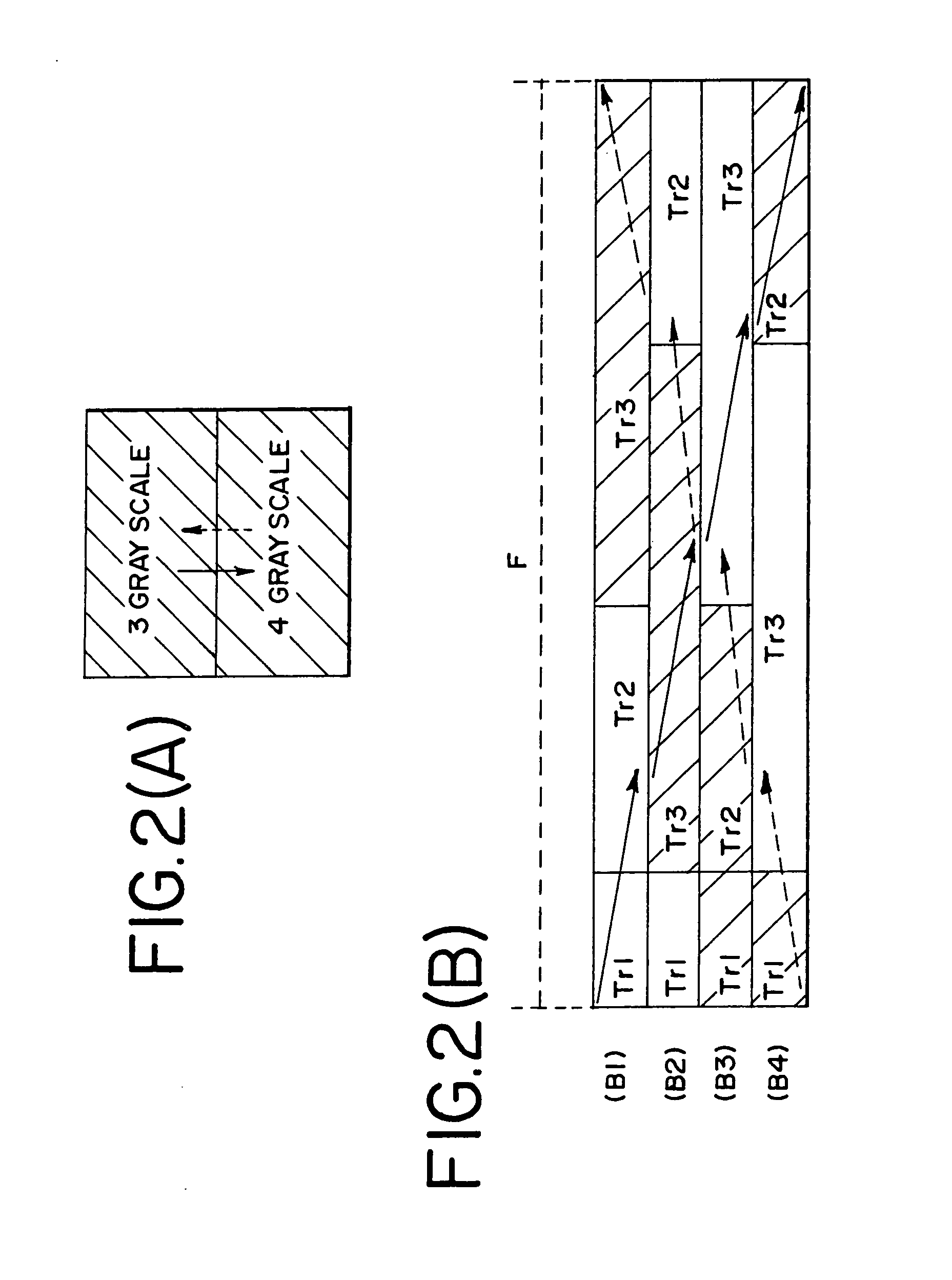
[0080]Embodiment Mode 1 is explained while referring to FIGS. 1A to 1C2. FIG. 1A shows a display image of a pixel portion in which m columns×n rows of pixels are arranged in a matrix shape. A 3-bit of a digital video signal capable of displaying gray scales 1 to 8 is input to each of the pixels, and an image is displayed. Pixels in the upper half of the pixel portion perform display of the number 3 gray scale, and pixels in the lower half of the pixel portion perform display o...

embodiment mode 2

[0181]An embodiment mode of the present invention is explained below. Note that the display device and the method of driving the display device of the present invention, are not limited to the example shown below. In Embodiment Mode 2, there is shown a structure in which the starting time of frame periods differs greatly between odd number lines of pixels and even number lines of pixels. In other words, the order of appearance of subframe periods is the same for the odd number lines of pixels and the even number lines of pixels in Embodiment Mode 2, but the times at which the frame periods, structured by the subframe periods, begin are shifted greatly.

[0182]Embodiment Mode 2 is explained with reference to FIGS. 6A to 6C. Elements that are the same as those of Embodiment Mode 1 have the same reference numerals attached. FIG. 6A shows pixel portion display. Similar to the display of FIG. 1A, an image is displayed in FIG. 6A using a 3-bit of the digital video signal capable of displayi...

embodiment mode 3

[0249]In Embodiment Mode 3, the order of appearance of subframe periods, and the time at which the subframe periods begin, are changed between odd number lines of pixels and even number lines of pixels.

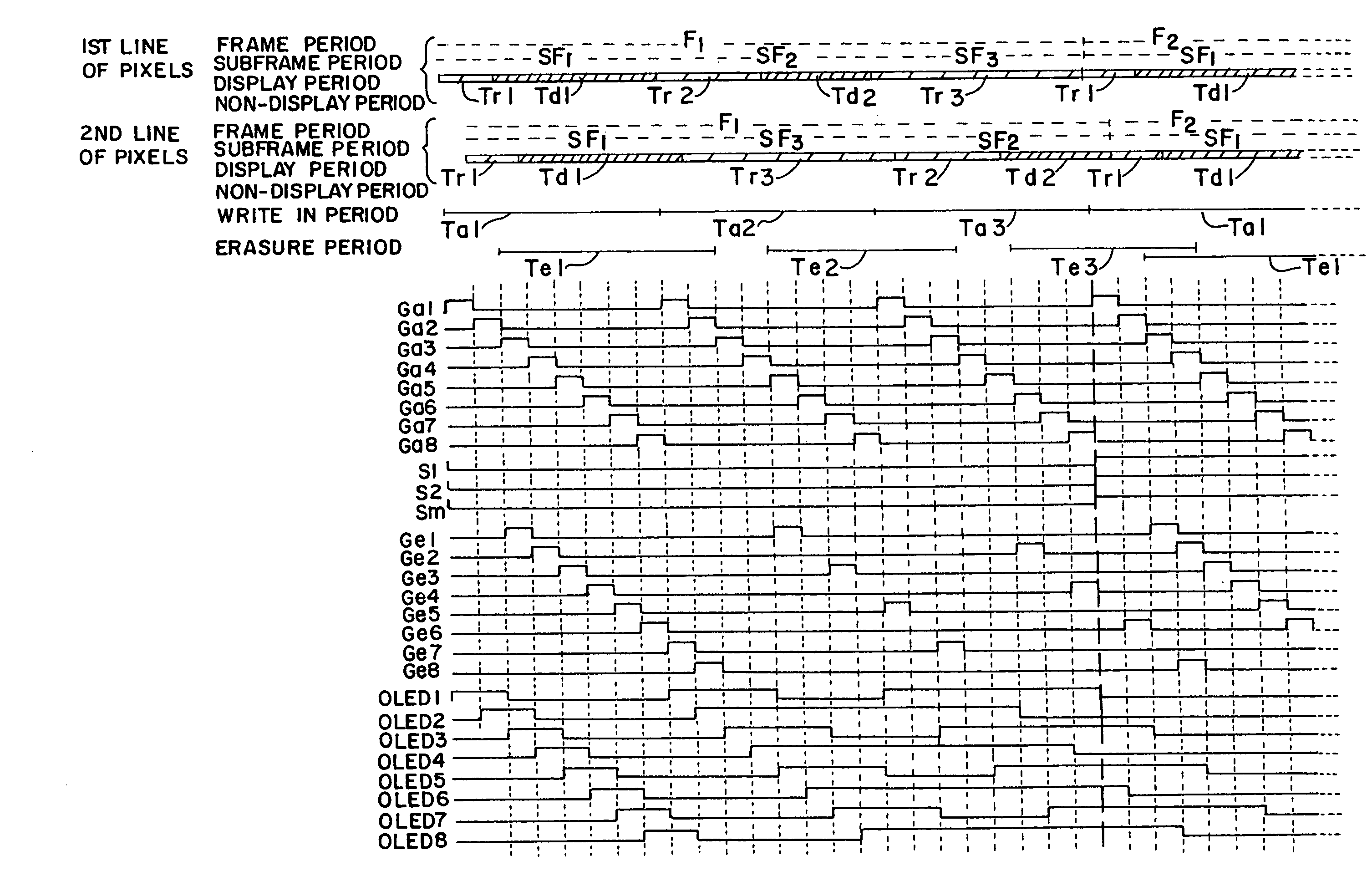
[0250]The structure of Embodiment Mode 3 is explained using FIG. 10. Elements that are the same as those of FIG. 5 and FIG. 9 have the same reference numerals attached. The frame periods, the subframe periods, the display periods, and the non-display periods for the number 1 line of pixels, and the frame periods, the subframe periods, the display periods, and the non-display periods for the number 2 line of pixels are shown for convenience of description in the figure.

[0251]The subframe periods appear in the frame period F1 in a sequence of the number 1 bit subframe period SF1, the number 2 bit subframe period SF2, and the number 3 bit subframe period SF3 in the odd number lines of pixels (the number 1 line of pixels, for example).

[0252]The subframe periods appear in the frame period ...


PUM

PropertyMeasurementUnit
thicknessaaaaaaaaaa
thicknessaaaaaaaaaa
thicknessaaaaaaaaaa

Abstract

False contouring during display by time division gray scales can be prevented with high efficiency. The order of appearance of subframe periods, and the times at which the subframe periods begin, are changed between pixels driven by odd number gate signal lines and pixels driven by even number gate signal lines. For example, assume that display is performed in a display period Tr1 of a subframe period SF1, a display period Tr2 of a subframe period SF2, and a display period Tr3 of a subframe period SF3. The order of appearance of the display periods is changed between pixels driven by the odd number gate signal lines (B1) and pixels driven by the even number gate signal lines (B2). Although the non-light emitting display periods (display periods Tr3, Tr2, and Tr1) are continuous over nearly one frame period in the odd number lines of pixels when there is a gray scale change, non-light emission and light emission are repeated alternately at the same time for the even number lines of pixels. Accordingly, the brightness of the above light emission is averaged by human eyes, and therefore the generation of unnatural dark lines (false contouring) can be suppressed.

Description

BACKGROUND OF THE INVENTION[0001]1. Field of the Invention[0002]The present invention relates to a display device and to a method of driving the display device. Specifically, the present invention relates to a display device in which frame periods are structured by a plurality of subframe periods, the display device having a method of controlling the brightness of light emission by using the subframe periods as one of methods of controlling gray scales. The present invention also relates to a method of driving the display device.[0003]2. Description of the Related Art[0004]Along with the arrival of computerized industrial society, the demand for thin, flat-panel displays has increased recently, and the development of display devices using organic light emitting elements (hereinafter referred to as organic light emitting displays) has flourished. Organic light emitting displays are of self light emitting type, and a back light is unnecessary. Therefore, they are easier to be made thi...

Claims


Application Information

Patent Timeline
Patent Type & Authority Patents(United States)
IPC IPC(8): G09G3/30H01L51/50G02F1/133G09G3/20G09G3/32
CPCG09G3/3258G09G3/2022G09G2300/0426G09G2300/0842G09G2300/0861G09G2320/0266G09G2310/0251G09G2320/02G09G2320/0247G09G2320/0261G09G2310/0224G02F1/133
Inventor KIMURA, HAJIME
Owner SEMICON ENERGY LAB CO LTD
Why Eureka
Try Eureka