
Support device for a trolling motor

a support device and trolling motor technology, which is applied in the direction of marine propulsion, vessel construction, transportation and packaging, etc., can solve the problems of metal fatigue on the flange, annoying impact noise, and inducing stress on the components of the trolling motor, so as to increase the compressibility and increase the deformability of the support pad

Active Publication Date: 2007-10-23
BRUNSWICK CORPORATION
View PDF14 Cites 29 Cited by
  • Summary
  • Abstract
  • Description
  • Claims
  • Application Information

AI Technical Summary

Benefits of technology

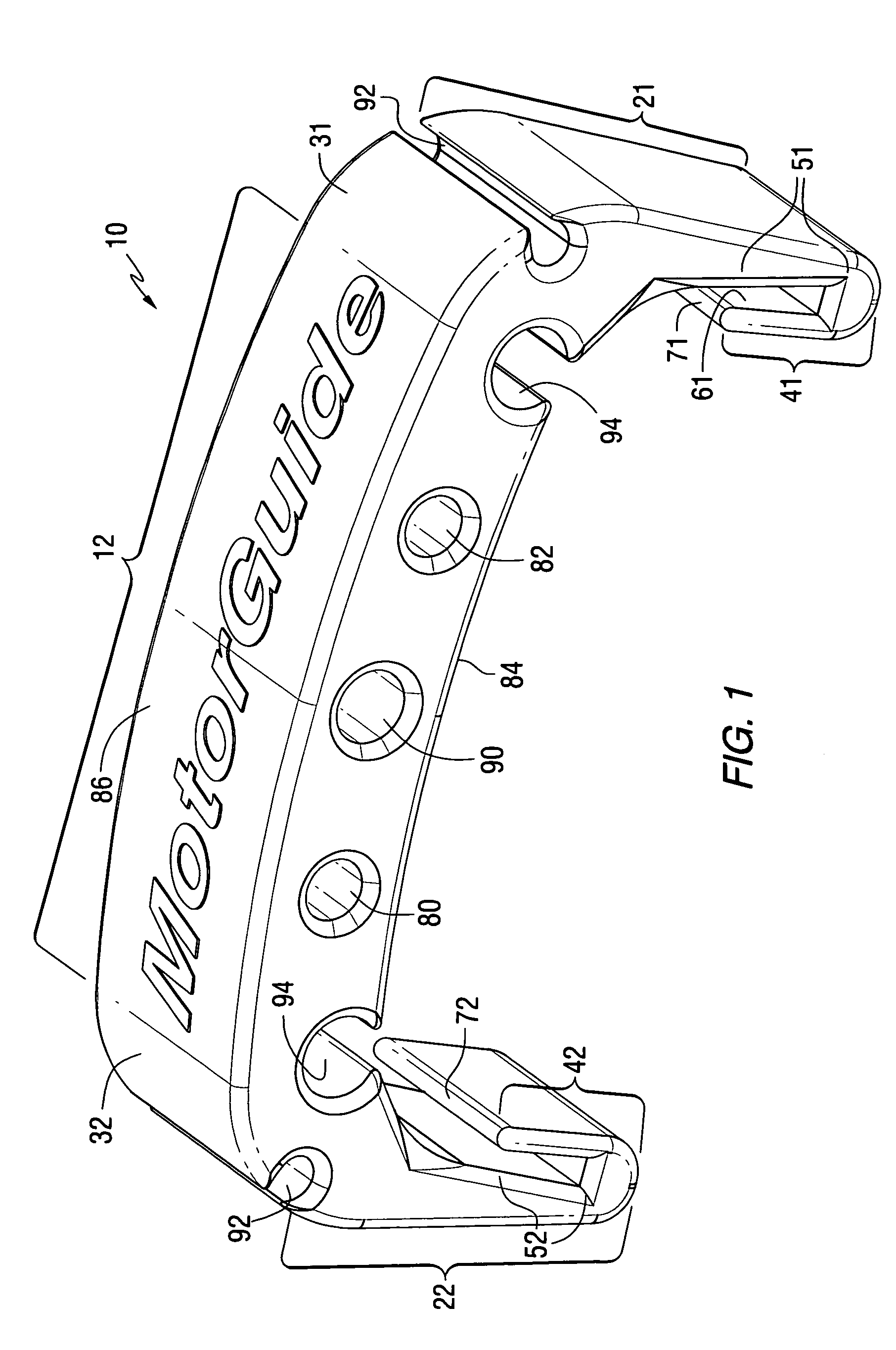
[0021]The present invention can further comprise a first distal end extending from the first retention member and a second distal end extending from the second retention member. The first and second distal ends can both extend in overlapping relation over first and second portions, respectively, of the first and second retention members in order to define first and second gaps, respectively, therebetween. The first and second gaps can be shaped to receive first and second sidewalls of the arm of the trolling motor and, in certain preferred embodiments of the present invention, the first and second gaps can be tapered to decrease in dimension toward the termini of the first and second distal ends. At least one cavity can be formed in the support pad in order to increase its compressibility. The support pad can comprise an inner surface and an outer surface. The inner surface is configured to be in contact with the arm of the trolling motor when the support device is attached to the arm of the trolling motor. The outer surface faces away from the arm of the trolling motor. An expansion cavity is formed, in a particularly preferred embodiment of the present invention, in the support pad and configured to increase the deformability of the support pad. A cord retention slot can be formed in the support pad and shaped to retain a pull cord therein. An electrical cable retention slot can be formed in the support pad and shaped to retain a transducer cable therein.

Problems solved by technology

Stress forces will most likely cause metal fatigue to occur on the flange called the “positive stow lock feature” near the pivot point.
This can induce stress on the components of the trolling motor and, in certain instances, can cause annoying impact noises if the cantilevered arm of the trolling motor repeatedly strikes the deck surface.

Method used


Image

  • Support device for a trolling motor
  • Support device for a trolling motor
  • Support device for a trolling motor

Examples


Embodiment Construction

[0029]Throughout the description of the preferred embodiment of the present invention, like components will be identified by like reference numerals.

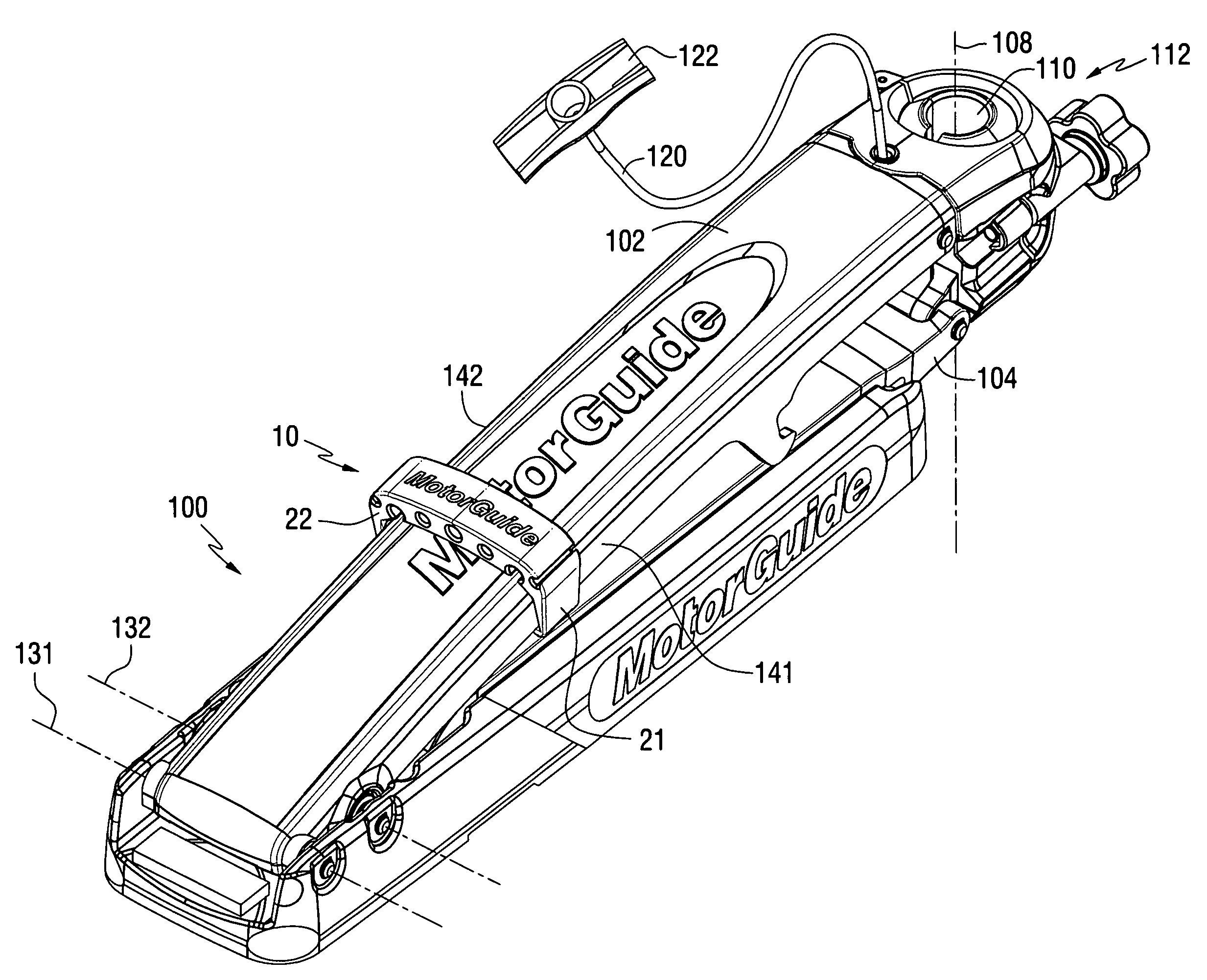
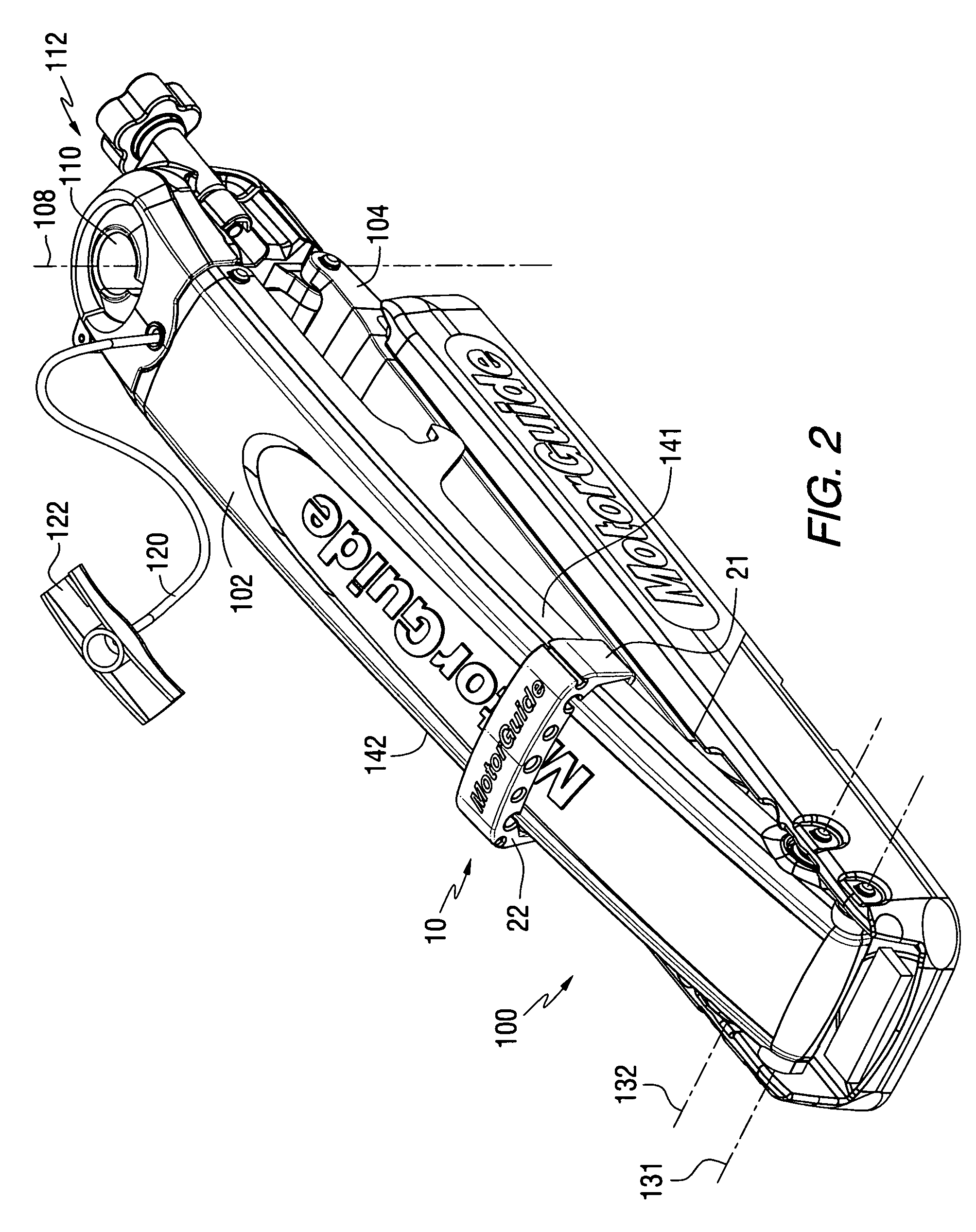
[0030]FIG. 1 shows the support device of a preferred embodiment of the present invention. It is intended to be attached to an arm of a trolling motor in a manner that will be described in greater detail below. The support device comprises a support pad 12 that is shaped to extend across a width of an arm of the trolling motor. A first retention member 21 and a second retention member 22 are attached to first and second ends, 31 and 32, of the support pad 12. The first and second retention members, 21 and 22, are configured to retain the support pad 12 in position relative to the arm of the trolling motor.

[0031]With continued reference to FIG. 1, a first distal end 41 and a second distal end 42 extend from the first and second retention members, 21 and 22. The first distal end 41 extends in overlapping relation over a first portion 51 of...


PUM


Abstract

A support device for a trolling motor is attachable to an arm of the trolling motor to provide a cushion between the arm and a deck surface of a boat. This cushion inhibits bouncing of the arm of the trolling motor in response to a boat traveling over rough water or being trailered from one location to another over roads. The support device is attachable to the arm of the trolling motor without additional fasteners, such as screws or clips. It is also movable to different positions along the length of the arm of the trolling motor, thus allowing more than one support device to be attached to the trolling motor mount.

Description

BACKGROUND OF THE INVENTION[0001]1. Field of the Invention[0002]The present invention is generally related to a support device for a trolling motor and, more particularly, to a support device that can be easily attached to an extendable arm of a trolling motor to provide support between the arm and the deck of a boat when the trolling motor is in a retracted or stowed position.[0003]2. Description of the Related Art[0004]Many different types of trolling motor devices are well known to those skilled in the art. Typically, a trolling motor is configured so that it can easily be deployed for use and, alternatively, retracted for storage when not in use.[0005]U.S. Pat. No. 3,861,628, which issued to Krieger on Jan. 21, 1975, describes a folding accessory bracket assembly that is particularly adapted for mounting a trolling motor so as to automatically position the accessory vertically in the water in an extended position and parallel to and on top of the boat deck in a retracted positio...

Claims


Application Information

Patent Timeline
Patent Type & Authority Patents(United States)
IPC IPC(8): B60L11/00
CPCB63H20/007B63H21/305B63H20/02
Inventor JANITZ, MIKEL E.
Owner BRUNSWICK CORPORATION
Learn More