Modular terminal device

a terminal device and module technology, applied in the direction of coupling device connection, electrical apparatus casing/cabinet/drawer, gaseous cathode, etc., can solve the problem of unnecessary cos

Active Publication Date: 2007-10-23
PASS SEYMOUR
View PDF13 Cites 64 Cited by
  • Summary
  • Abstract
  • Description
  • Claims
  • Application Information

AI Technical Summary

Problems solved by technology

This requires that an electrical installer carry an inventory of an a...

Method used


Image

  • Modular terminal device
  • Modular terminal device
  • Modular terminal device

Examples


Embodiment Construction

[0020]Reference will now be made in detail to the present embodiments of the invention, examples of which are illustrated in the accompanying drawings. Whenever possible, the same reference numerals will be used throughout the drawings to refer to the same or like parts.

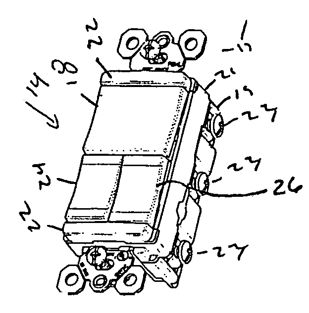
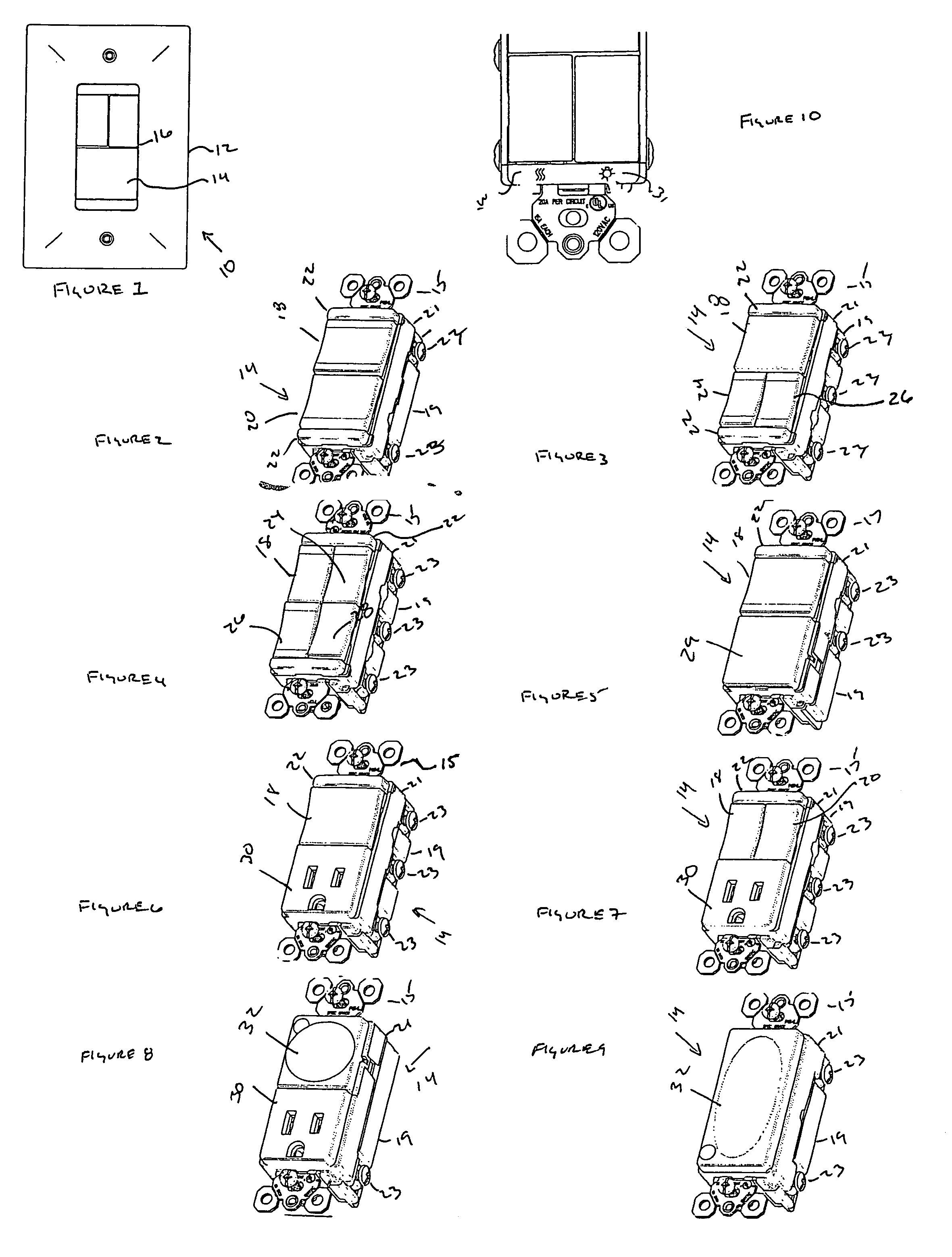
[0021]One embodiment of the electrical device of the present invention is shown in FIG. 1 and is designated generally throughout by the reference numeral 10. The electrical device 10 includes a wall plate 12 and an electrical wiring device 14.

[0022]The wall plate includes a single rectangular 16 opening configured to receive any one electrical wiring device 14 from a plurality of differently configured electrical wiring devices. In an alternative embodiment, the opening 16 in the wall plate 12 is sized to accommodate a plurality of electrical wiring devices 14 installed in a single wall box in an abutting relationship to one another.

[0023]Each of the electrical wiring devices 14 includes a ground strap 15. The ground...


PUM


Abstract

The present invention includes a modular electrical device for use in an electric circuit. The modular electrical device includes a wall plate defining a first opening, and a housing configured to be disposed within the first opening. The housing is configured to accommodate a frame member selected from the plurality of frame members. Each frame member is configured to accommodate at least one wiring assembly. The modular electrical device further includes an electrical wiring assembly chosen from a plurality of electrical wiring assemblies. Each of the plurality of electrical wiring assemblies has a different functional configuration, and each of the plurality of electrical wiring devices being sized to fit in the selected frame member. The modular electrical device further includes a set of terminal contacts selected from a plurality of sets of terminal contacts. Each set of terminal contacts is matched to accommodate one of the plurality of electrical wiring assemblies.

Description

CROSS-REFERENCE TO RELATED APPLICATIONS[0001]This is a continuation of U.S. patent application Ser. No. 10 / 726,128 filed on Dec. 2, 2003 now U.S. Pat. No. 6,989,489, the content of which is relied upon and incorporated herein by reference in its entirety, and the benefit of priority under 35 U.S.C. § 120 is hereby claimed.BACKGROUND OF THE INVENTION[0002]1. Field of the Invention[0003]The present invention relates to an electrical wiring device and more particularly to an electrical wiring device suitable for commercial and residential use.[0004]2. Background of the Invention[0005]Typically, wall mounted conventional electrical devices for use in residential or commercial applications such as offices require a wall plate specifically configured for the electrical device. For example, each switch, receptacle, or hallway light typically employs its own wall plate opening. Installation of multiple devices may require multiple gang wall plates and multiple gang wall boxes. This requires...

Claims


Application Information

Patent Timeline
IPC IPC(8): H02G3/08
CPCH02G3/086H01H23/025H01R13/6691H01R24/76H01R2103/00H01R13/7135
Inventor SAVICKI, JR., GERALD R.
Owner PASS SEYMOUR
Why Eureka
Try Eureka