System and method for aggregating multiple radio interfaces into a single logical bridge interface

a radio interface and logical bridge technology, applied in the field of wireless networks, can solve the problems of difficult physical connection between buildings, difficulty in aggregating multiple radio interfaces into a single logical bridge interface, and high cost of methods,

Active Publication Date: 2007-10-23
CISCO TECH INC
View PDF6 Cites 30 Cited by
  • Summary
  • Abstract
  • Description
  • Claims
  • Application Information

AI Technical Summary

Problems solved by technology

Although connecting several computers or portable devices within a single building can readily be accomplished via the use of a LAN infrastructure, difficulties often arise when more than one building or site, needing connection to the infrastructure, are involved.
Unfortunately, this method is expensive, time consuming and sometimes even not feasible.
For example, a physical connection between buildings may not be possible when buildings are several miles apart or separated by natural obstacles (e.g. rivers, streams).
However, because these conventional bridges operate on a single public band radio link, they are susceptible to outages due to a variety of conditions (e.g. interference).
Because conventional switches correspond to a single radio link, the corresponding data rate is greatly impacted by the limitations of the single radio link.
Multiple active paths between LAN segments cause loops in the network that may result in rapid frame duplication and “network storms”.
While transparent to end stations, the STP recalculation, or reconfiguration, makes recovery from a failed conventional wireless bridge cumbersome, slow and costly.
Further, traditional wireless bridge products do not leverage or utilize catalyst switch (e.g. software / firmware / ASIC) logic.

Method used


Image

  • System and method for aggregating multiple radio interfaces into a single logical bridge interface
  • System and method for aggregating multiple radio interfaces into a single logical bridge interface
  • System and method for aggregating multiple radio interfaces into a single logical bridge interface

Examples


Embodiment Construction

[0021]The following includes examples of various embodiments and / or forms of components that fall within the scope of the present system that may be used for implementation. Throughout this description, the preferred embodiment and examples shown should be considered as exemplars, rather than limitations, of the present invention.

[0022]Although the embodiments of present system and method described herein are directed toward an IEEE 802.11 wireless network, it will be appreciated by one skilled in the art that the present concepts and innovations described herein are applicable to alternate wired and wireless networks and network protocols, without departing from the spirit and scope of the present innovation.

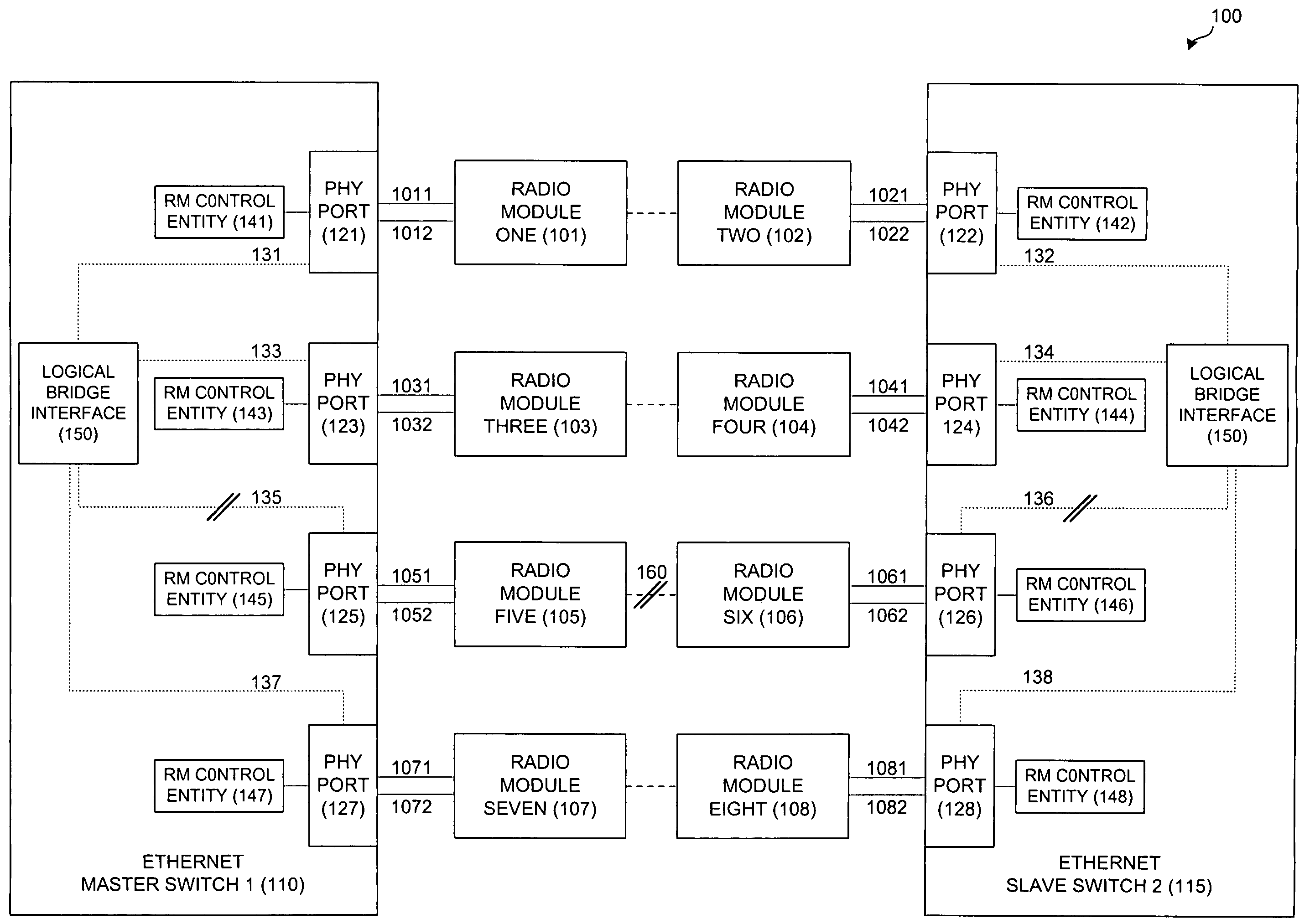
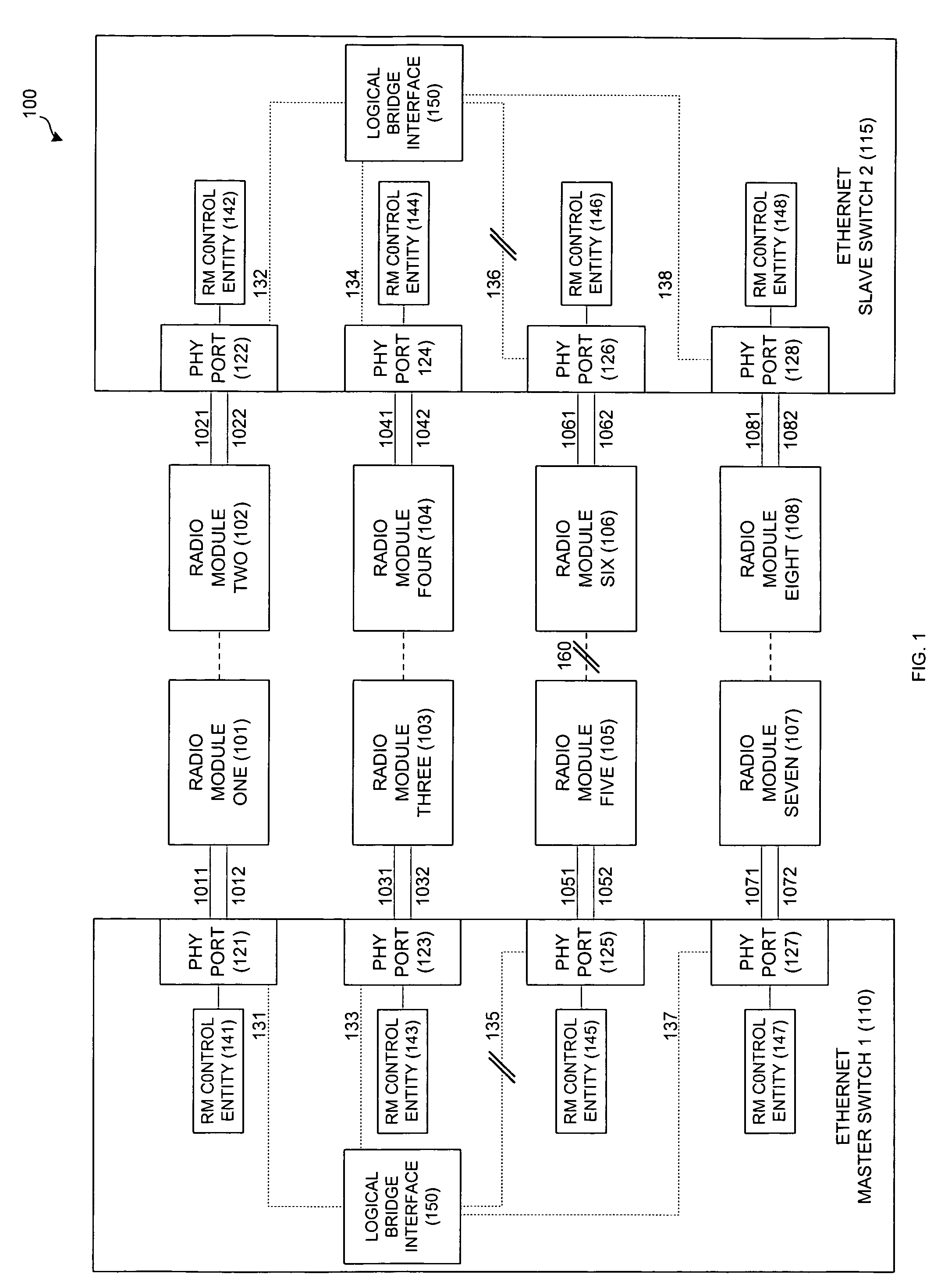
[0023]By way of background, to establish a radio link or interface, an Ethernet switch communicates with an attached Radio Module (RM) over a logical Control Link and a logical Ethernet Link. Multiple logical Ethernet links and corresponding wireless (e.g. 802.11) links are agg...


PUM


Abstract

A system and method for aggregating multiple radio interfaces into a single logical bridge interface with reference to an IEEE 802.11 Wi-Fi network and an Ethernet local area network. The system includes a master switch with multiple associated wireless modules. Each master switch wireless module selectively broadcasts an associated connection signal. The master switch has an associated aggregation port, which is in data communication with each of the master switch wireless modules and selectively routes data among the master switch wireless modules. The system also includes a slave switch with multiple associated wireless modules. Each of the slave switch wireless modules receives one associated connection signal and establishes a wireless data communication link with the broadcasting master switch. The slave switch also includes an associated aggregation port, which is in data communication with each of the slave switch wireless modules, selectively routes data among the slave switch wireless modules.

Description

BACKGROUND OF THE INVENTION[0001]The present innovation relates generally to wireless networks and, more specifically to a protocol for aggregating multiple radio interfaces into a single logical bridge interface.[0002]Local Area Networks (LANs) are widely used to provide interconnectivity between computers affiliated with a building or site. Typically, LAN's consist of multiple computers connected together by a hardwired network or system backbone. For example, a typical system backbone is an Ethernet or Token Ring based system. A server or host computer will also be connected to the backbone and serve as a central controller for the particular LAN. Multiple LAN segments are interconnected by devices called “bridges” or “switches”.[0003]Advances in technology have enabled LAN's to be used to interconnect wireless devices, such as laptop computers, personal data assistants and even Voice-over-Internet-Protocol telephones. In wireless networks, access points are connected to the LAN ...

Claims


Application Information

Patent Timeline
Patent Type & Authority Patents(United States)
IPC IPC(8): H04L12/50H04B1/38H04L12/28H04L12/46H04L47/41H04W4/06H04W40/02H04W76/02H04W88/14H04W92/02
CPCH04L12/4625H04L47/125H04W92/02H04W4/06H04W76/02H04L47/41H04W88/14H04W76/10
Inventor MEIER, ROBERT C.
Owner CISCO TECH INC
Why Eureka
Try Eureka