
Automatic planning of network configurations

a network configuration and automatic planning technology, applied in the field of automatic planning of network configurations, can solve the problems of brute force approaches, large number of users' problems, complex and time-consuming task of automation unit engineering,

Inactive Publication Date: 2006-02-02
SIEMENS AG
View PDF5 Cites 8 Cited by
  • Summary
  • Abstract
  • Description
  • Claims
  • Application Information

AI Technical Summary

Benefits of technology

[0006] The object of the present invention is therefore to specify a device and a method, which reduce the outlay required when searching for a suitable network configuration, particularly in the field of automation.
[0011] The device and method described are used to generate a configuration in limited computing time, which connects all the devices to form a functional network, takes account of existing construction rules, complies with any quality of service criteria and usage limits set and is as economical as possible to set up.

Problems solved by technology

The engineering of automation units in particular is a complex and time-intensive task.
While the engineering of PROFIbus structures is wholly controlled, the concept of Ethernet networks is still problematic for a large number of users, in particular when quality of service criteria such as end-to-end delay times and usage limits have to be complied with.
In principle the search for a network architecture represents an NP class problem.
For large numbers of users therefore brute force approaches, which are means for resolving difficult problems in the areas of IT and game theory and involve trying out all variants, soon become impractical.
However until now such tools have tended to be considered in isolation and often require the repeated inputting of already available information in a more or less identical form.

Method used


Image

  • Automatic planning of network configurations
  • Automatic planning of network configurations
  • Automatic planning of network configurations

Examples


Embodiment Construction

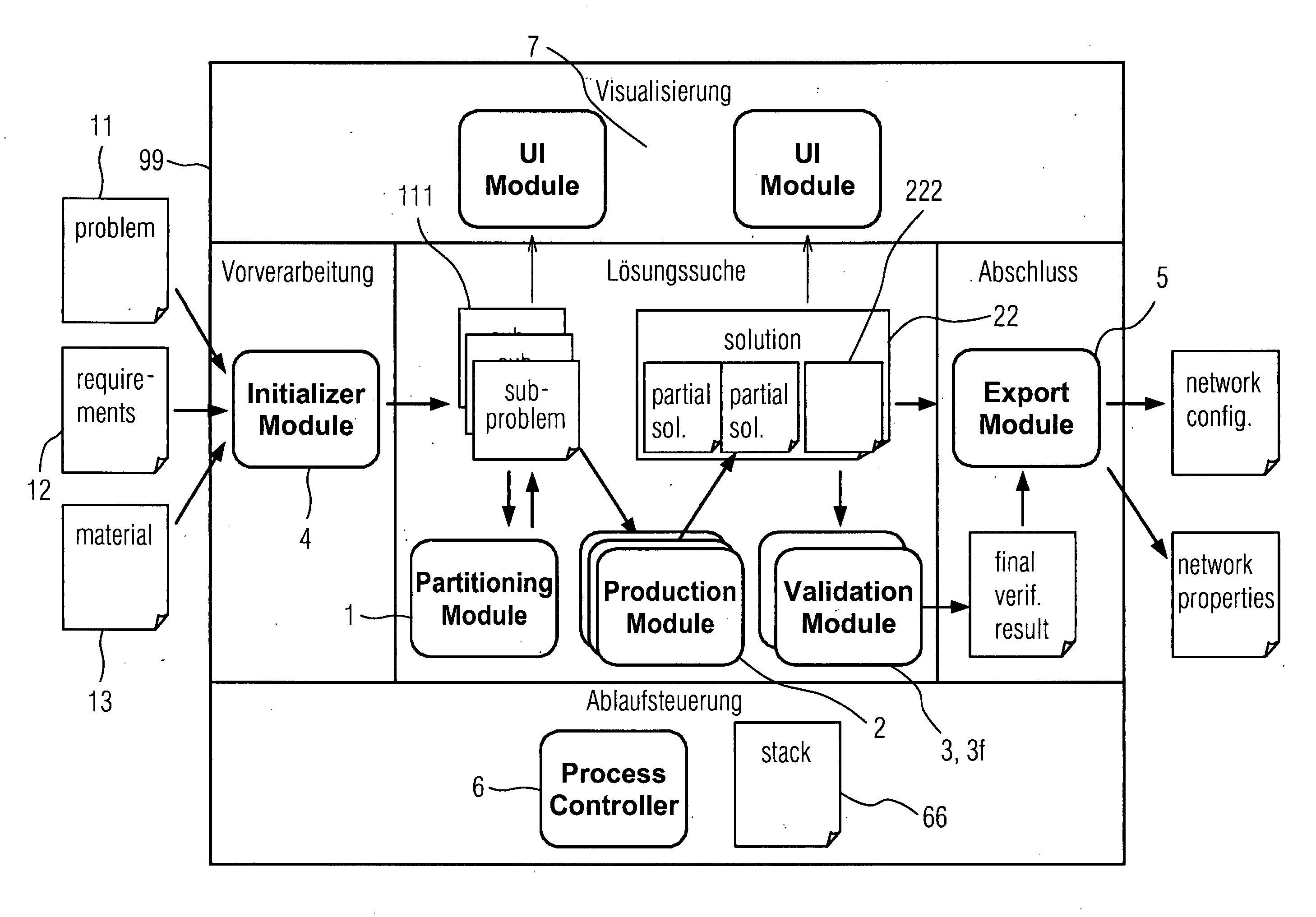
[0019]FIG. 1 shows a schematic diagram of the device for the automatic planning of network configurations. The algorithm for generating the network is embedded in a framework 99, which provides a series of services, data structures and interfaces as elements of a network design infrastructure.

[0020] The framework 99 contains one or a plurality of partition modules 1, each of which breaks a network planning problem 11 down into sub-problems 111. A description model for a network planning problem 11 also exists as does an initialization model 4 for reading in the input data for a network planning problem 11. One or a plurality of production modules 2 then generate(s) partial solutions 222 to the network planning problems 11 according to defined rules. One or a plurality of validation modules 3, 3f verify / ies the generated partial solutions 222 and complete a final acceptance test for the overall solution 22.

[0021] The device also has a process controller 6 for the solution process, ...


PUM


Abstract

The invention relates to a device and a method, which reduce the outlay required when searching for a suitable network configuration, in particular in the field of automation. The device for the automatic planning of a network configuration, in particular for an automation system, comprises at least one partition module to break down at least one described network planning problem into sub-problems, at least one production module to generate at least one solution to each of the sub-problems of the at least one network planning problem based on predefinable rules and at least one validation module to verify the generated solutions to the sub-problems. The purpose of the device and the method according to the invention for automatic network planning is to support the planning process for network structures for major systems, in particular for systems with more than 1000 users, by supplying suitable methods and tools. One of the focal areas is switch-based Ethernet-LANs, as used for example in PROFInet environments.

Description

CROSS REFERENCE TO RELATED APPLICATIONS [0001] This application claims priority to the European application No. 04018287.5, filed Aug. 2, 2004 and which is incorporated by reference herein in its entirety. FIELD OF INVENTION [0002] The invention relates to the automatic planning of network configurations. SUMMARY OF THE INVENTION [0003] The engineering of automation units in particular is a complex and time-intensive task. Complex automation units are distributed and are frequently based on multilevel network architectures such as field buses (e.g. PROFIbus) and higher-order Ethernet-based factory networks. In this process the boundaries between traditional field buses and higher networks become increasingly blurred (e.g. PROFInet). While the engineering of PROFIbus structures is wholly controlled, the concept of Ethernet networks is still problematic for a large number of users, in particular when quality of service criteria such as end-to-end delay times and usage limits have to b...

Claims


Application Information

Patent Timeline
IPC IPC(8): G06F15/173H04L12/24
CPCH04L41/08H04L41/16H04L41/145H04L41/0889
Inventor KROGER, REINHOLDMACHENS, HOLGER
Owner SIEMENS AG
Learn More