
Method For Ethernet and Electric Power Cabling

a technology of ethernet and electric power cabling, applied in the field of network infrastructure, can solve the problems of limiting themselves to light points and power sockets, requiring a lot of retrofit wiring, and few sockets originally planned to be inadequate, so as to achieve the effect of simple installation

Inactive Publication Date: 2008-08-28
INNOMEDIA TECH PVT
View PDF5 Cites 9 Cited by
  • Summary
  • Abstract
  • Description
  • Claims
  • Application Information

AI Technical Summary

Benefits of technology

[0015]The object of the present invention is therefore to provide a network infrastructure, which would become as ubiquitous as the electrical infrastructure, while being much simpler to install.
[0017]A further object of the present invention is to provide a premise-wide wiring system, which systematically covers each and every room, and to provide an optimal way for wiring the entire premise thereby saving a lot of energy in evaluating different options.
[0022]In carrying out the above objects, a methodology is provided for Ethernet and electrical cabling comprising the steps of: providing wiring to a premise through an entry point; providing wiring in each room of the premise at a skirting level; wiring leaving the premise through the entry point; wherein said wiring includes at least a pair of Ethernet cable and at least a pair of electrical cable forming a recursive loop beading thereby enabling installation of Ethernet and electrical appliances at any point and emerging need.

Problems solved by technology

As a result, over the years, as the need for connecting to new appliances such as air-conditioners and tube-lights emerged, a lot of retrofit wiring was required.
The few sockets planned originally turned out to be inadequate and people had to use electric extension boards to connect more appliances.
However, the residents have to limit themselves to the light points and power sockets as originally visualized by the builder, or else resort to exposed, retrofit wiring.
Any subsequent change to the concealed wiring was therefore unthinkable.
The situation is, however, worse as there is no perceived need for Broadband appliances in each room: unlike the need for an electric bulb.
The traditional structured LAN wiring cost can be quite high, making it unaffordable for residential usage.
An additional problem in modern homes is that of the neat interiors with concealed wiring for electricity, telephone and cable-TV.
These modern homes would not like any retrofit exposed wiring to spoil up the decor.
The major problems associated with the presently known methods of wiring are their connection complexities, requirement of networking expertise, poor scalability and high entry costs.
Another drawback of the existing electrical infrastructure, inside a premise is its fail-safe infrastructure where any loose contact, a cut wire or a blown fuse, can bring down the appliances connected to it.

Method used


Image

  • Method For Ethernet and Electric Power Cabling
  • Method For Ethernet and Electric Power Cabling
  • Method For Ethernet and Electric Power Cabling

Examples


Embodiment Construction

[0047]In the following description, specific details are set forth in order to provide an understanding of the invention. Reference in the specification to “one embodiment,”“a preferred embodiment” or “an embodiment” means that a particular feature, structure and characteristic, or function described in connection with the embodiment is included in at least one embodiment of the invention. The appearance of the phrase “an embodiment,”“in embodiment,” or the like in various places in the specification are not necessarily all referring to the same embodiment.

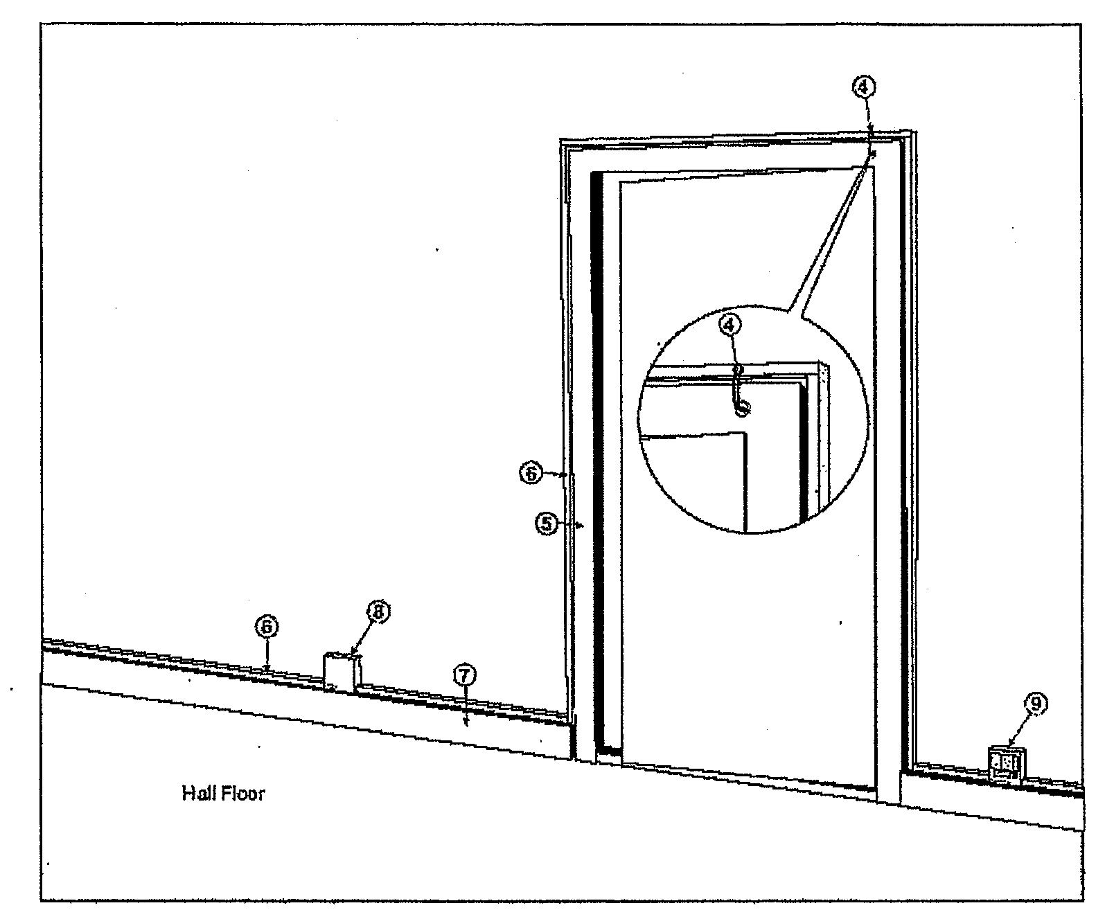
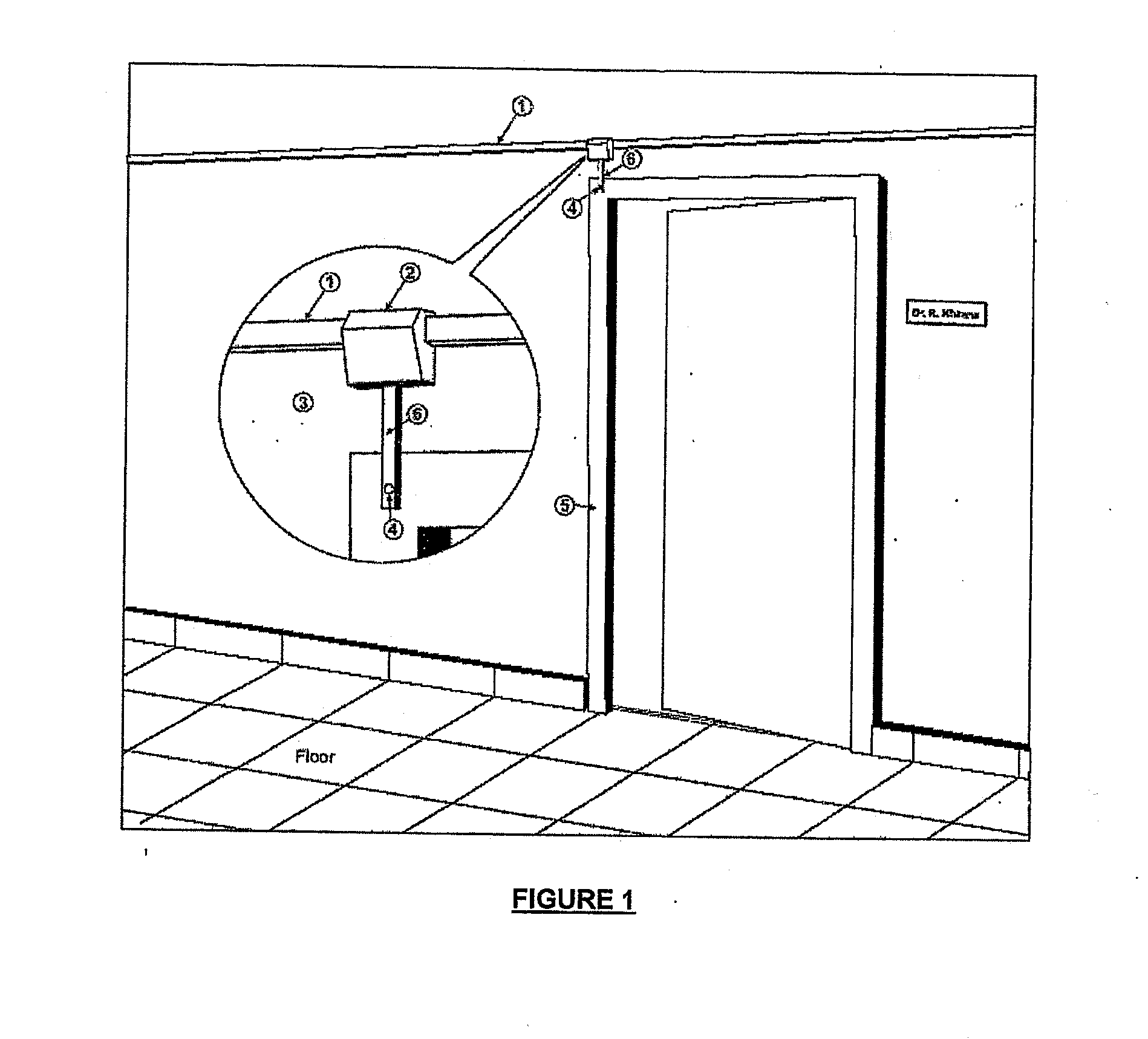
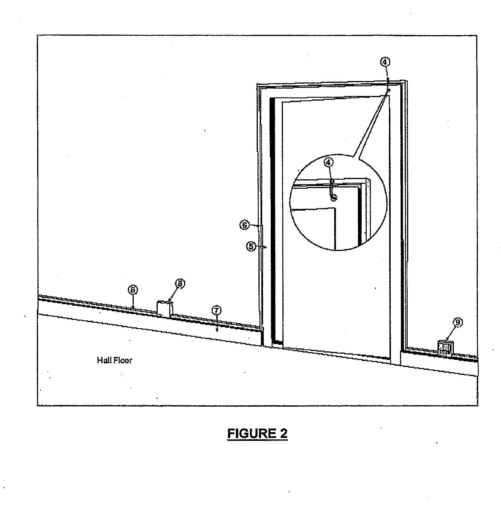
[0048]In an embodiment of the present invention, FIG. 1 shows a Premise Box (2) located on a Casing / Capping (1) coming from an external Gateway. The Premise Box is directly above the front door (5) of a Premise. A Beading (6) emerges from the Premise Box and enters the Premise through a hole (4) in the main door frame (5). This results in the interiors of a premise with a neat skirting level (7) on each wall and few inches above t...


PUM


Abstract

Present invention outlines a structured wiring methodology for installing a premise-wide distributed Ethernet LAN (Local Area Network) featuring Broadband Points with Power-over-Ethernet (PoE) and Electrical Sockets, allowing connection to Broadband Appliances. The necessary LAN and electrical cabling stays entirely within a Beading (or Casing and Capping), which recursively loops along the skirting level of the walls within the premise. This does not disturb the aesthetics of an existing premise, as the Beading merges with the skirting outline, or can be concealed within the wall itself. Each end of the looped Beading can be terminated on a dual Broadband Gateway, which provides WAN and global Internet connectivity. The looped Beading provides immunity against a single failure of Electronic boards (within Broadband Points or Gateway) or single cut in the cables. Ethernet connection cord can be as thin and flexible as that in telephones, and thinner than that for USB appliances. Furthermore, at the appliance end it is possible to use a tiny RJ-11 plug (used in telephones), which can get embedded within the appliance itself, instead of the traditional RJ-45 plug, which is bigger. The thin connection cord and the tiny RJ-11 plug, is more compact than the USB cord and connector, and doesn't have the latter's restriction of length and the available DC power. The Broadband appliances thus can tap the full bandwidth of 100 MB Ethernet, while not compromising on handling and ergonomic aspects.

Description

FIELD OF INVENTION[0001]The present invention relates to network infrastructure and more particularly to a method of cabling a premise-wide wiring system for systematically covering each and every room and locating broadband points anywhere in the premise.BACKGROUND OF THE INVENTION[0002]In the early days of electrical infrastructures, there was a need present for wiring up each room and corridor of the house so that bulbs, fans etc. could be used wherever required. There was a need, from the beginning, to provide electrical sockets in every room for connecting to electric appliances such as heaters, table lamps etc.[0003]The electric wiring, till quite recently was exposed, and done in quite an ad-hoc manner, depending on the perceived needs at the time of installation. As a result, over the years, as the need for connecting to new appliances such as air-conditioners and tube-lights emerged, a lot of retrofit wiring was required. The few sockets planned originally turned out to be ...

Claims


Application Information

Patent Timeline
Patent Type & Authority Applications(United States)
IPC IPC(8): H02G3/00
CPCH04L12/28H04L12/10
Inventor TAMBE, MOHAN
Owner INNOMEDIA TECH PVT
Learn More