Lasers for synchronized pulse shape tailoring

a technology of synchronized pulse and tailoring, which is applied in the field of lasers for synchronized pulse shape tailoring, can solve the problems of limited practical ways of changing pulse width or temporal power profile of a given laser medium, practical difficulties in achieving focused beam, and high repetition rate operation of e-o devices

Active Publication Date: 2007-10-30
ELECTRO SCI IND INC
View PDF73 Cites 11 Cited by
  • Summary
  • Abstract
  • Description
  • Claims
  • Application Information

AI Technical Summary

Benefits of technology

[0010]In some embodiments, the common resonator section includes a high reflectivity mirror, while each subresonator section has its own output port. The laser profile characteristics from each subresonator can then be recombined outside of the resonator while many of the adverse consequences of laser pulse jittering may be significantly reduced. The distinct profiles of the subsresonator outputs can be subjected to different optional harmonic conversion techniques before the profiles are recombined into a laser output pulse, permitting the laser output pulse to have a specially tailored profile using more than one laser wavelength. In other embodiments, such different wavelength profiles can be controlled to occur at different times with respect to each other.

Problems solved by technology

Once the resonator is constructed, there are few practical ways for changing the pulse width or temporal power profile for a given laser medium at a given pumping level and pulse repetition rate.
Lasers employing a fast diode master oscillator / fiber amplifier (MOPA) configuration can deliver substantially square energy profile laser pulses with an adjustable pulse width of about 1 ns-10 ns, but current fiber amplifiers deliver random unpolarized laser output and typically have a disadvantageous wider wavelength spectrum output that imposes practical difficulties in achieving focused beam spot sizes that are sufficiently small to perform the desired micromachining operations without adversely affecting nearby substrates or other materials.
However, operating the E-O devices at high repetition rates, especially above about 40 kHz, and synchronizing the laser pulses and the action(s) of an E-O device to a desired accuracy are extremely difficult to achieve under practical constraints.
However, in practice, combinations of such independently produced pulses suffer from laser pulse jitter, which is a random fluctuation of laser pulse initiation relative to laser pulse initiation control signals that is inherent to typical Q-switched lasers.
This synchronization problem becomes more significant at high repetition rates, especially above about 40 kHz, for example.

Method used


Image

  • Lasers for synchronized pulse shape tailoring
  • Lasers for synchronized pulse shape tailoring
  • Lasers for synchronized pulse shape tailoring

Examples


Embodiment Construction

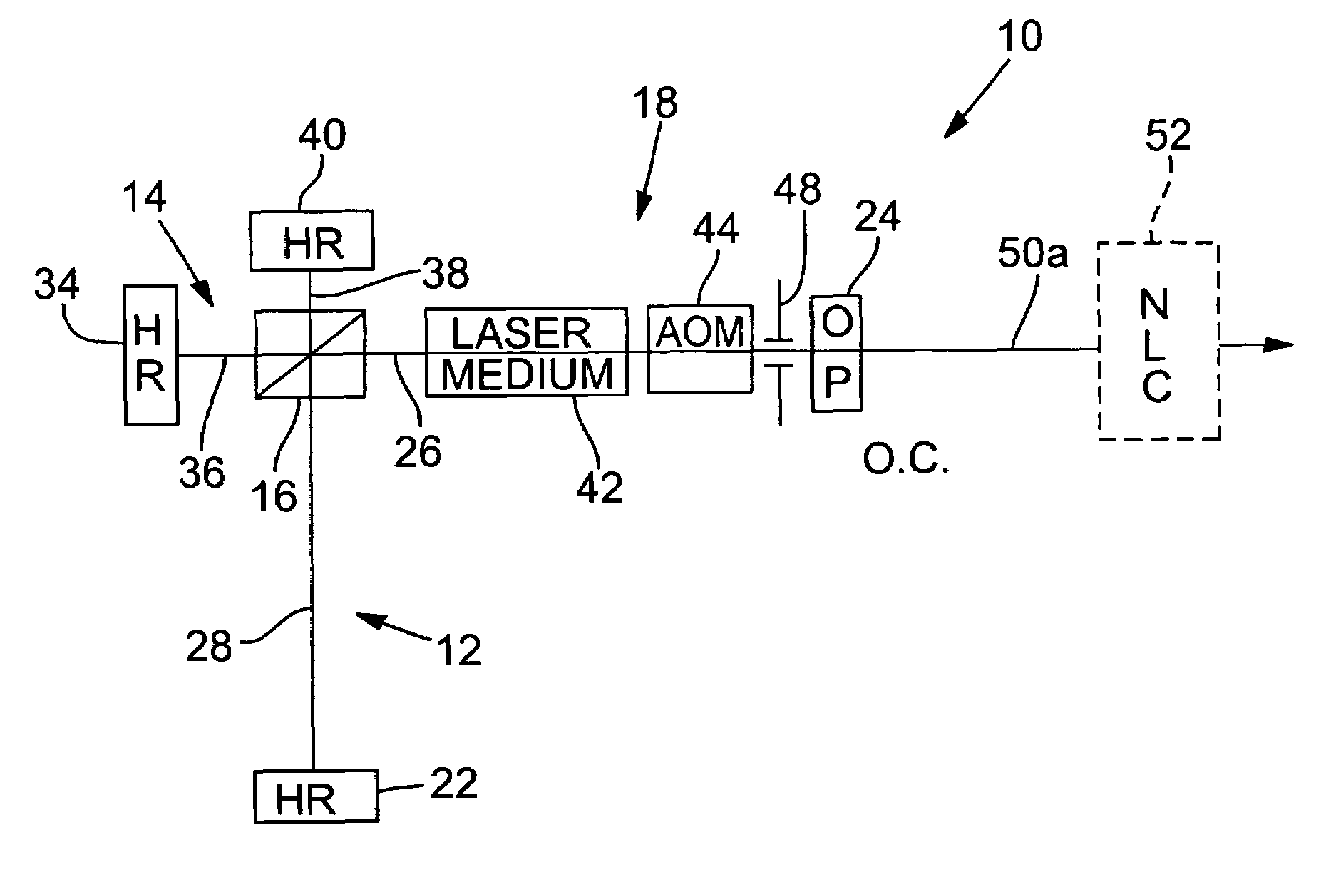
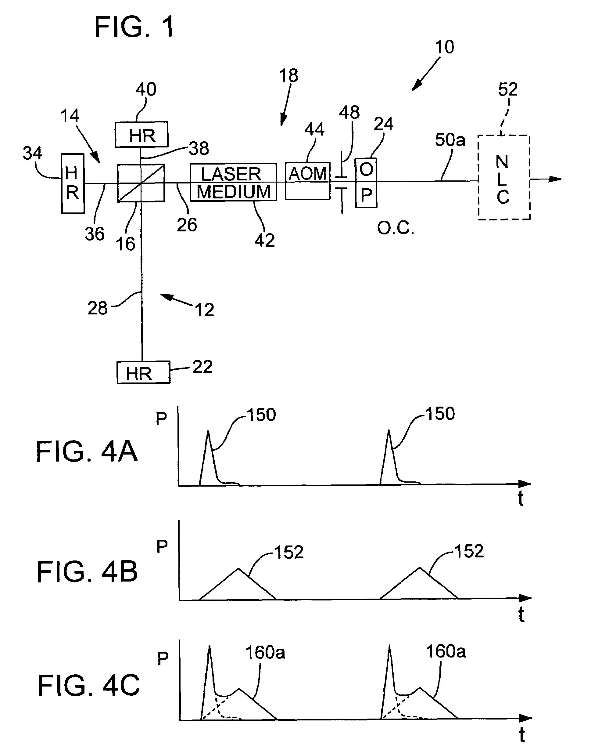
[0021]FIG. 1 is a schematic diagram of a laser 10 having a long subresonator 12 and a short subresonator 14 that are integrated with a beamsplitter 16 to employ a common resonator section 18. The beamsplitter 16 may be a mirror that is partly reflective and transmissive to permit oscillation to be established substantially simultaneously in both the long subresonator 12 and the short subresonator 14. The beamsplitter 16 may alternatively be a polarizer which will allow the oscillation of a substantially p-polarized laser beam in the short subresonator 14 and a substantially s-polarized laser beam in the long subresonator 12.

[0022]With reference to FIG. 1, the long subresonator 12 is defined by a long subresonator mirror 22 and an output port 24 that are positioned along an optical path 26. The long subresonator 12 includes the common resonator section 18 and a long subresonator section 28. The short subresonator 14 can be defined by a short subresonator mirror 34 and the output port...


PUM

PropertyMeasurementUnit
rise timeaaaaaaaaaa
rise timeaaaaaaaaaa
harmonic wavelengthsaaaaaaaaaa

Abstract

A plurality of subresonators (12, 14), having different design configurations, share a common resonator section (18) such that the lasing action can be substantially synchronized to provide coherent laser pulses that merge the different respective pulse energy profile and / or pulse width characteristics imparted by the configurations of the subresonators (12, 14). The subresonators (12, 14) may share a laser medium (42) in the common section, or each distinct subresonator section (28, 36) may have its own laser medium (42). Exemplary long and short subresonators (12, 14) generate specially tailored laser pulses having a short rise time and a long pulse width at one wavelength or two different wavelengths that may be beneficial for a variety of laser and micromachining applications including memory link processing.

Description

RELATED APPLICATIONS[0001]This patent application claims benefit of U.S. Provisional Application No. 60 / 635,053, filed Dec. 9, 2004.COPYRIGHT NOTICE[0002]© 2005 Electro Scientific Industries, Inc. A portion of the disclosure of this patent document contains material that is subject to copyright protection. The copyright owner has no objection to the facsimile reproduction by anyone of the patent document or the patent disclosure, as it appears in the Patent and Trademark Office patent file or records, but otherwise reserves all copyright rights whatsoever. 37 CFR § 1.71(d).TECHNICAL FIELD[0003]Controlling laser pulse width and / or power profile can be enhanced by employing a laser having two or more subresonators that share a common section.BACKGROUND OF THE INVENTION[0004]Diode-pumped (DP), solid-state (SS) lasers running at high pulse repetition rates are employed widely in a variety of applications including laser micromachining. In these lasers, the pulse width is largely determi...

Claims


Application Information

Patent Timeline
Patent Type & Authority Patents(United States)
IPC IPC(8): H01S3/082
CPCB23K26/063H01S3/082H01S3/07H01S3/0805H01S3/08086H01S3/1611H01S3/10038H01S3/10046H01S3/109H01S3/117H01S3/127H01S3/083B23K26/0622
Inventor SUN, YUNLONGSUN, LEI
Owner ELECTRO SCI IND INC
Why Eureka
Try Eureka