Apparatus and method for monitoring bulk tank cryogenic systems

a cryogenic system and apparatus technology, applied in the field of monitoring systems for bulk tank cryogenic storage systems, can solve the problems of unsafe levels of co2 /sub>gas, both employees of the establishment and customers may be exposed without their knowledge, beverage dispensing machines will cease to operate correctly, etc., to reduce or eliminate undesirable consequences of co2 gas flow, the effect of quick and easy termination

Active Publication Date: 2011-04-05
ODONNELL KEVIN P
View PDF16 Cites 9 Cited by
  • Summary
  • Abstract
  • Description
  • Claims
  • Application Information

AI Technical Summary

Benefits of technology

[0011]A system for monitoring and controlling the delivery of CO2 from a bulk storage tank to at least one gas-driven pump is disclosed. By monitoring certain conditions, the flow of CO2 can be quickly and easily terminated if necessary, thereby reducing or eliminating undesirable consequences of CO2 gas flow in abnormal operational scenarios. The invention is particularly well suited for deployment in conjunction with beverage dispensing machines and can be configured to shut down the flow of CO2 if a drop in pressure occurs due to a leak in the system or if a syrup delivery system runs out of product.

Problems solved by technology

If this gas is accumulated in sufficient density in a closed space, such as a storage room, it may be hazardous, if not lethal.
In such situations, both employees of the establishment and customers may be exposed to unsafe levels of CO2 gas without their knowledge.
This typically necessitates some type of a service call, since when this occurs, the beverage dispensing machine will cease to operate correctly.
Service calls of this type are unscheduled and are may be quite expensive, driving up the operating costs of the entire system.

Method used


Image

  • Apparatus and method for monitoring bulk tank cryogenic systems
  • Apparatus and method for monitoring bulk tank cryogenic systems
  • Apparatus and method for monitoring bulk tank cryogenic systems

Examples


Embodiment Construction

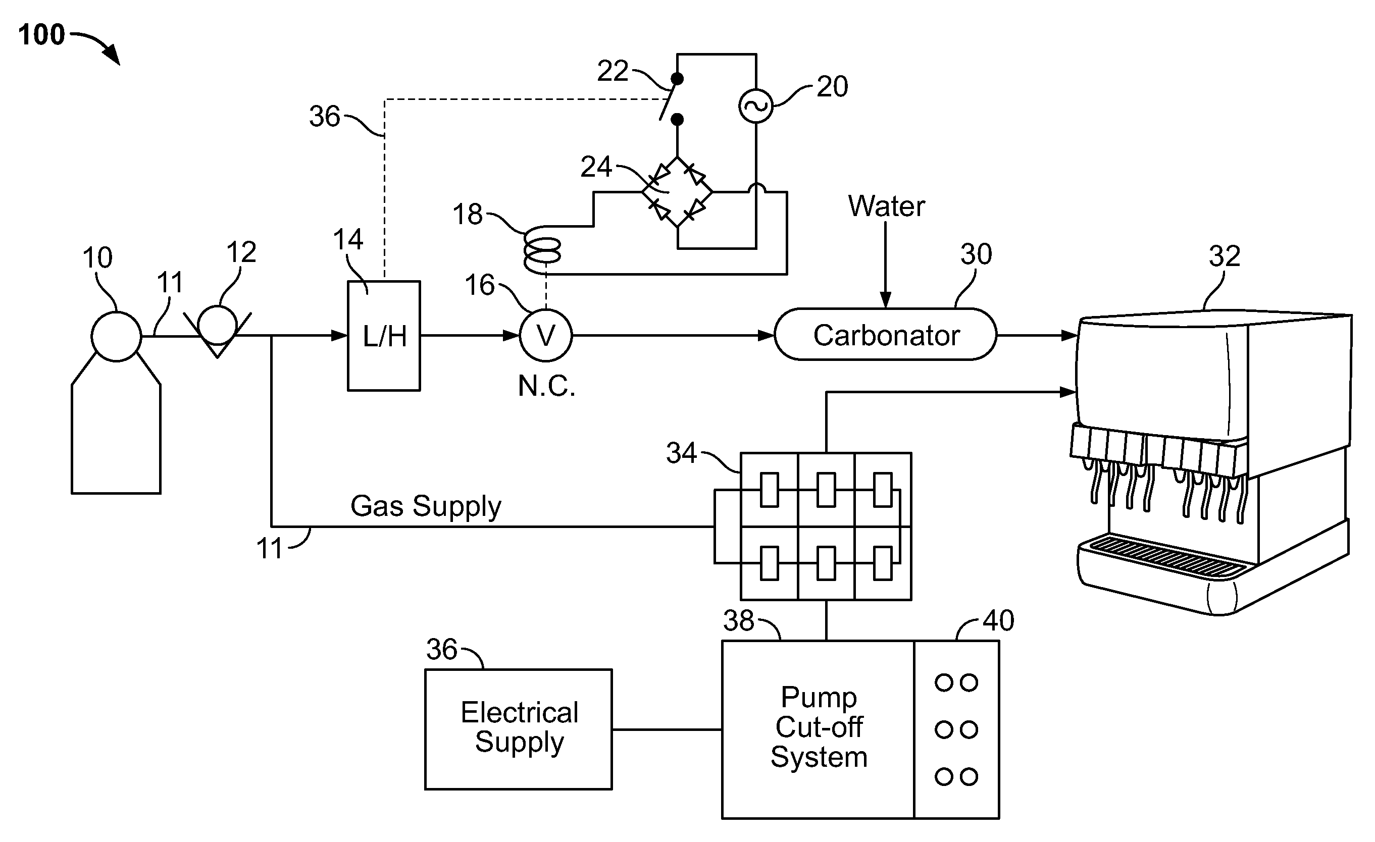
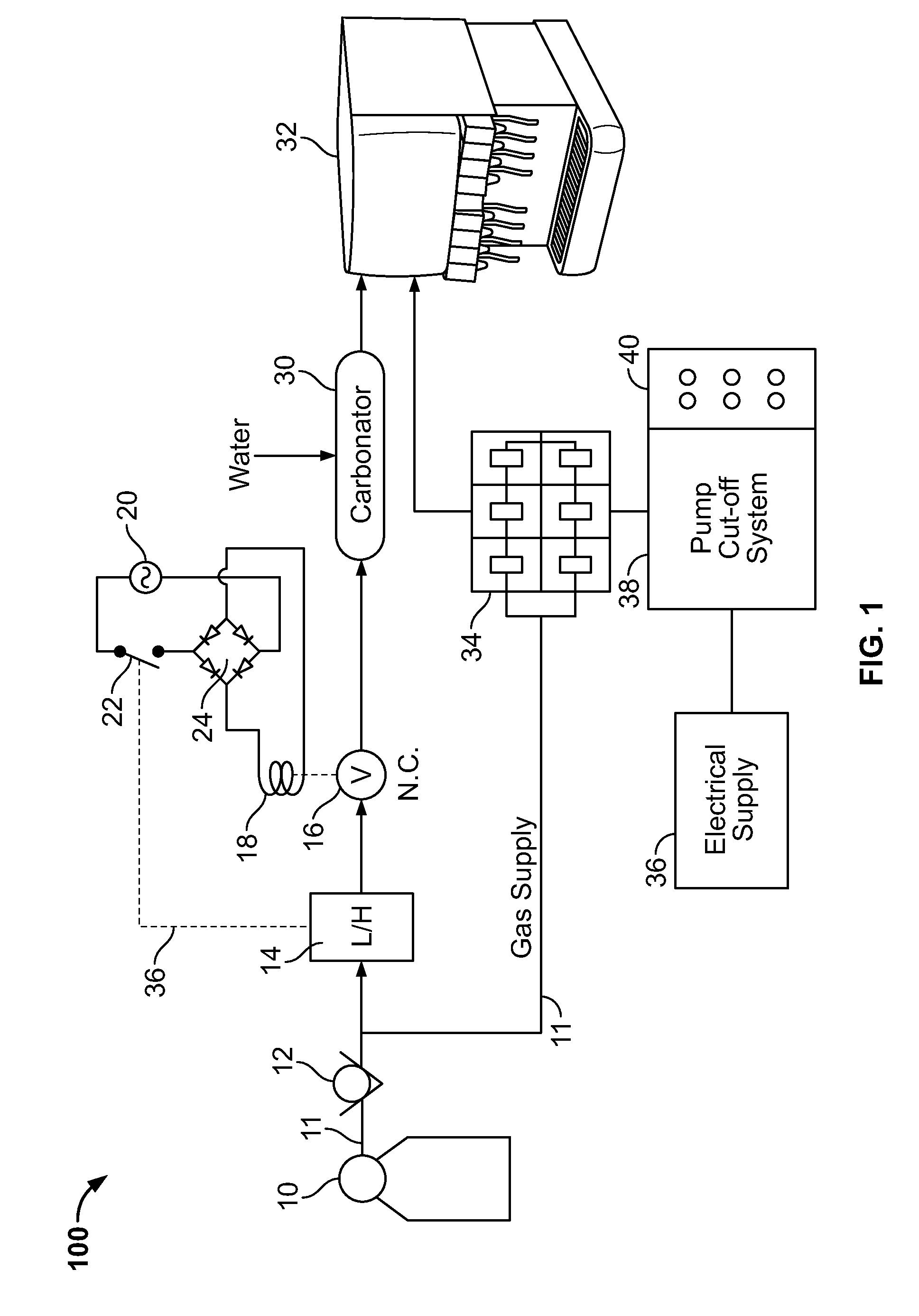
[0017]Referring now to FIG. 1, a block diagram of a system 100 for monitoring and controlling the flow of CO2 in accordance with a preferred exemplary embodiment of the safety system of the present invention is depicted. As shown in FIG. 1, system 100 is used in conjunction with a bulk cryogenic storage tank 10 of the type used to store and deliver liquid CO2, converted to a gaseous state, suitable for application in a variety of applications.

[0018]One such application is shown in FIG. 1 is the use of bulk cryogenic storage tank 10 in conjunction with a beverage dispensing unit 32. Beverage dispensing unit 32 is fairly common and is used in many fast food restaurants and the like to dispense soft drinks A gas delivery line 11 is connected to a conventional high pressure regulator 12, which regulates the output gas flow from the tank 10 to a pressure in the approximate range of 90 to 110 PSI. Pressure regulator 12 and the pressure range for the CO2 gas delivered from tank 10 is relat...


PUM


Abstract

A system for monitoring and controlling the delivery of CO2 from a bulk storage tank to at least one gas-driven pump is disclosed. By monitoring certain conditions, the flow of CO2 can be quickly and easily terminated if necessary, thereby reducing or eliminating undesirable consequences of CO2 gas flow in abnormal operational scenarios. The invention is particularly well suited for deployment in conjunction with beverage dispensing machines and can be configured to shut down the flow of CO2 if a drop in pressure occurs due to a leak in the system or if a syrup delivery system runs out of product.

Description

CROSS REFERENCE TO RELATED APPLICATION[0001]This non-provisional patent application claims the benefit of U.S. patent application Ser. No. 12 / 070,958, under 35 U.S.C. §120, which application was filed on 22 Feb. 2008, which application is now pending and which application is incorporated by reference herein.BACKGROUND OF THE INVENTION[0002]1. Technical Field[0003]The present invention generally relates to systems for storing gas and relates more specifically to monitoring systems for bulk cryogenic storage systems.[0004]2. Background Art[0005]The use of bulk cryogenic storage systems for carbon dioxide (CO2) gas is a relatively recent historical development in the beverage industry. Vacuum jacketed storage containers delivering 300 pounds to 750 pounds or more of liquified CO2 gas are widely used. These containers are configured to deliver gaseous CO2 at pressures above 90 pounds per square inch by converting the liquid CO2 to gas using a natural conversion process through a simple ...

Claims


Application Information

Patent Timeline
Patent Type & Authority Patents(United States)
IPC IPC(8): B67D1/00
CPCF17C7/00F17C2270/05F17C2201/056F17C2203/0391F17C2205/0326F17C2205/0338F17C2221/011F17C2221/013F17C2221/031F17C2223/0123F17C2223/0161F17C2223/033F17C2223/035F17C2225/0123F17C2225/0146F17C2225/033F17C2225/035F17C2227/0142F17C2227/0185F17C2250/032F17C2250/036F17C2250/043F17C2250/0443F17C2250/0465F17C2250/0486F17C2250/0626F17C2250/072F17C2250/077F17C2260/032F17C2260/044F17C2265/04F17C2201/0119Y10T137/2569
Inventor O'DONNELL, KEVIN P.
Owner ODONNELL KEVIN P
Why Eureka
Try Eureka