Multistage pump

a multi-stage, pump technology, applied in the field of pumps, can solve the problems of reducing the life of the pump, reducing the efficiency of the pump, so as to reduce the recirculation of fluid within the pump

Active Publication Date: 2007-11-06
FRANKLIN ELECTRIC CO INC
View PDF4 Cites 29 Cited by
  • Summary
  • Abstract
  • Description
  • Claims
  • Application Information

AI Technical Summary

Problems solved by technology

A pump will, however, lose efficiency if water is re-circulated within a particular stage.
In addition, recirculation may also severely decrease pump life if abrasive particles are passed into the pump and dwell in the stage.

Method used


Image

  • Multistage pump
  • Multistage pump
  • Multistage pump

Examples


Embodiment Construction

[0020]Although the making and using of certain embodiments of the present invention are discussed in detail below, it should be appreciated that the specific embodiments discussed herein are merely illustrative of ways to make and use the invention, and do not delimit the scope of the invention. The drawings are not necessarily to scale and certain features may be shown in generalized or schematic form.

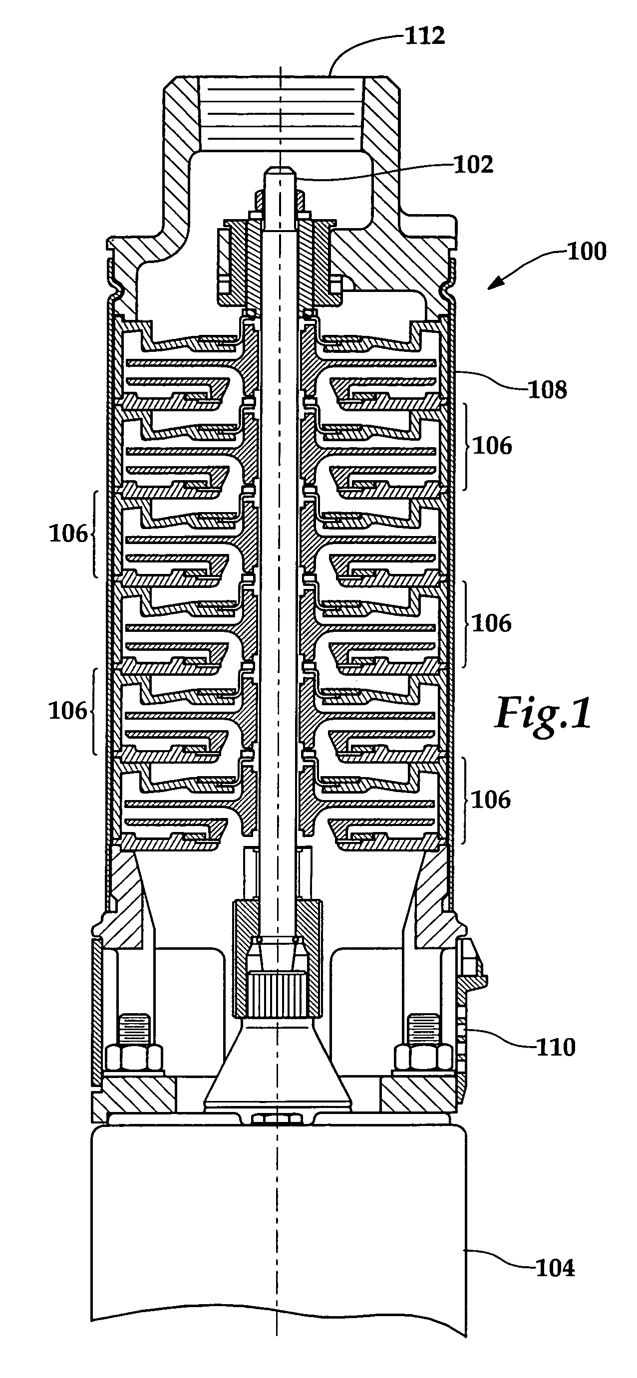
[0021]In one preferred embodiment, the present invention comprises a multistage pump assembly 100, as depicted in FIG. 1, having a main impeller shaft 102 rotatably driven by a motor 104. Preferably, plural pump stages 106 are disposed about main shaft 102 within a cylindrical pump case 108. The pump stages 106 driven by the main shaft 102 move fluid from a pump fluid inlet 110 to pump fluid outlet 112.

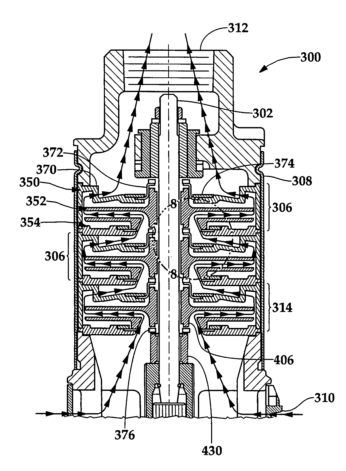
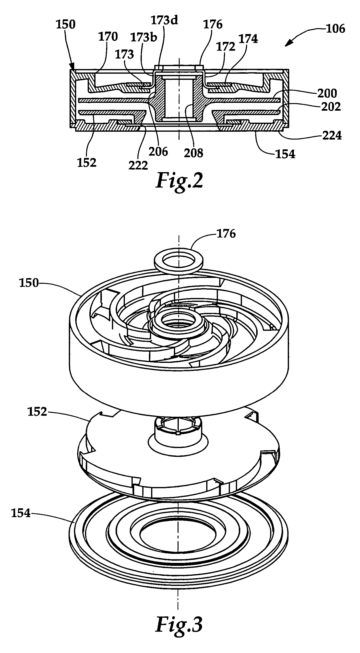
[0022]Each pump stage 106 comprises three sub-assemblies, as depicted in FIGS. 2 through 6. These sub-assemblies each comprise a diffuser assembly 150, an impeller assembly 152 and a di...


PUM


Abstract

A centrifugal pump includes plural pump stages, each comprising an impeller assembly, a stationary disc assembly and a diffuser assembly, all disposed about an impeller shaft. A floating impeller hub seal is supported by a diffuser assembly to minimize fluid recirculation. A thrust washer is disposed around the impeller shaft and is engageable with an impeller hub and the hub seal. A wear ring is secured to a disc assembly and engageable with a wear surface on the impeller.

Description

TECHNICAL FIELD OF THE INVENTION[0001]The present invention relates generally to pumps, and in particular to multistage submersible pumps.BACKGROUND OF THE INVENTION[0002]Submersible pumps are used throughout the world to pump water out of various well configurations. The submersible pump typically has a plurality of impellers which work in series to develop pressure within the pump. The water is expelled from the pump discharge and is therefore pressurized and available for usage. In general, a submersible pump will incorporate a number of impellers, or stages, which may vary in their respective diameters and port openings. Such pumps are commonly referred to as multistage pumps.[0003]Generally, the impellers of each stage of a multistage pump adds pressure to the water entering each stage. Accordingly, as the number of stages in a pump are increased, the pump's total output pressure also increases. A pump will, however, lose efficiency if water is re-circulated within a particular...

Claims


Application Information

Patent Timeline
Patent Type & Authority Patents(United States)
IPC IPC(8): F01D11/00
CPCF04D1/063F04D29/167F04D29/0413
Inventor VOLK, JAMES J.
Owner FRANKLIN ELECTRIC CO INC
Why Eureka
Try Eureka