[0014]These and other embodiments and benefits of the present invention will no doubt become obvious to those of ordinary skill in the art after having read the following best mode for carrying out the invention and viewing the various drawings.
[0015]FIG. 1 is a diagram of a single reference system of the prior art for providing reference phases to a rover station;
[0016]FIG. 1A is a diagram of a reference network positioning system of the prior art for providing reference phases to a rover station;
[0017]FIG. 2 is a diagram of a single reference positioning system of the present invention for providing synthetic reference phases to a rover station for adding a position error to a rover position;
[0018]FIG. 2A is a block diagram of a reference station for the system of FIG. 2;
[0019]FIG. 3 is a diagram of a reference network positioning system of the present invention for providing synthetic reference phases to a rover station for adding a position error to a rover position;
[0020]FIGS. 3A, 3B and 3C are block diagrams of first, second and third embodiments of a server for the positioning system of FIG. 3;
[0021]FIG. 4 is a diagram showing a secure rover station of the present invention for computing synthetic reference phases for adding a position error to a rover position operating in a single reference positioning system;
[0022]FIG. 4A is a block diagram of the rover station of FIG. 4; FIG. 5 is a diagram showing a secure rover station of the present invention for computing synthetic reference phases for adding a position error to a rover position in a reference network positioning system;
[0022]FIG. 4A is a block diagram of the rover station of FIG. 4; FIG. 5 is a diagram showing a secure rover station of the present invention for computing synthetic reference phases for adding a position error to a rover position in a reference network positioning system;
[0023]FIGS. 5A and 5B are block diagrams of first and second embodiments of the rover station of FIG. 5;
[0024]FIGS. 6A and 6B are block diagrams of first and second embodiments of random reference generators for providing synthetic reference phases for the present invention;
[0025]FIG. 7 is a diagram for a single reference positioning system of the present invention where a secure rover station dithers a secure position for providing an unsecure position having an added positional error;
[0026]FIGS. 7A and 7B are block diagrams of first and second embodiments of the positioning system of FIG. 7;
[0027]FIG. 8 is a diagram for a reference network positioning system of the present invention where a secure rover station dithers a secure position for providing an unsecure position having an added position error;
[0028]FIGS. 8A, 8B, 8C and 8D are block diagrams of first, second, third and fourth embodiments of the positioning system of FIG. 8;
[0029]FIG. 9 is a block diagram of a random position dither processor for the systems of FIGS. 7 and 8;
[0030]FIG. 10 is a flow chart of a method of the present invention for providing synthetic reference phases from a single reference positioning system to a rover station;
[0031]FIG. 11 is a flow chart of a method of the present invention for providing synthetic reference phases from a reference network positioning system to a rover station;
[0032]FIG. 12 is a flow chart of a method of the present invention for computing synthetic reference phases in a rover station operating in a single reference positioning system;
[0033]FIG. 13 is a flow chart of a method of the present invention for computing synthetic reference phases in a rover station operating in a reference network positioning system;
[0034]FIG. 14 is a flow chart of the method of the present invention for dithering a secure rover position for providing an added error to a rover position in a single reference positioning system; and
[0035]FIG. 15 is a flow chart of the method of the present invention for dithering secure rover position for providing an added error to a rover position in a reference network positioning system.
[0036]The details of the preferred embodiments for carrying out the idea of the invention will now be described. It should be understood that the description of these details is not intended to limit the invention to these details. On the contrary these details are merely intended to describe the best mode for carrying out the idea of the invention. Numerous alternatives, modifications and equivalents of the embodiments described herein will be apparent to someone skilled in the art as within the scope of the idea of this invention. The preferred embodiment of the invention is described for the global positioning system (GPS). However, it will be apparent to those in the art that the invention may be carried out with a generic global navigation satellite system (GNSS) including the global positioning system (GPS), the global orbiting navigation system (GLONASS), the Galileo system or a combination of these systems. It should also be noted that pseudolites may be used in place of satellites for broadcasting GNSS positioning signals.
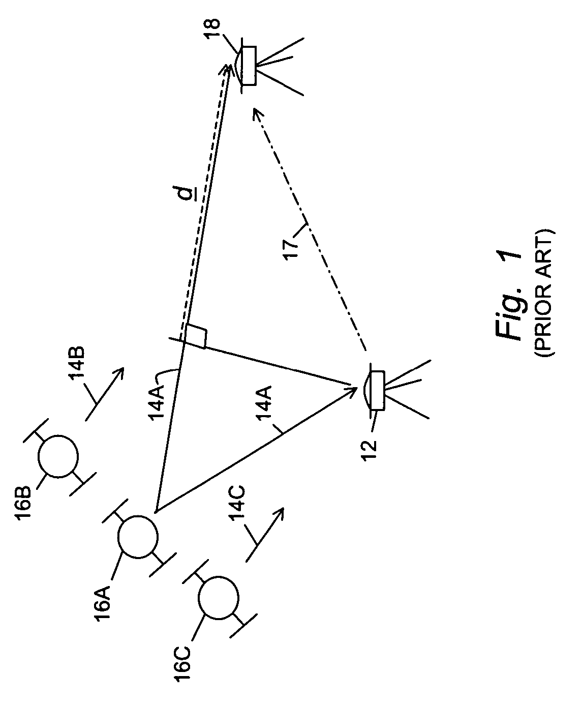
[0037]FIG. 1 is a diagram showing a conventional real time kinematic (RTK) global positioning system (GPS)-based system of the prior art. The reference station 12 includes a reference GPS receiver for receiving GPS signals 14, illustrated as 14A, 14B and 14C, from GPS satellites 16, illustrated as 16A, 16B and 16C. The reference station 12 measures the carrier phases of the GPS signals 14 and sends a radio signal 17 having reference data for the measured phases and reference geographical position to one or more rover stations shown as rover 18. The rover station 18 includes an RTK GPS receiver for measuring the carrier phases for the same GPS signals 14.
[0038]The difference between the reference and rover phase measurements yields estimates of perpendicular distance vectors represented by a vector d between the rover station 18 and the GPS satellite 16A. Measurements from several GPS satellites 16 yield estimates of several perpendicular distance vectors and ultimately the position of the rover station 18 with respect to the reference station 12. The vector d may be understood as a dot product of the vector between the GPS satellite 16 and the rover station 18 and the vector between the reference station 12 and the rover station 18. An exemplary RTK GPS system is described in U.S. Pat. No. 5,519,620, entitled “centimeter accurate global positioning system receiver for on-the-fly real-time-kinematic measurement and control” by Nicholas C. Talbot et al., incorporated herein by reference.
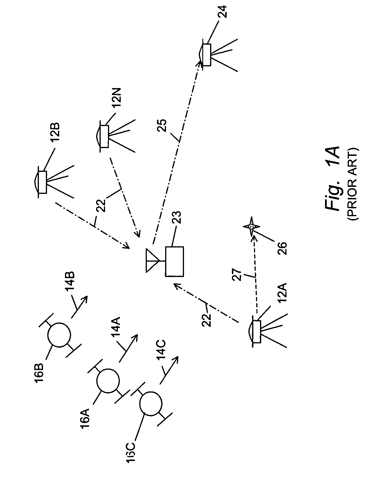
[0039]FIG. 1A is a diagram showing a virtual reference system (VRS) RTK GPS-based system of the prior art. Reference network stations 12A, 12B through 12N include reference GPS receivers for measuring carrier phases of the GPS signals 14 received from the GPS satellites 16. The reference stations 12A-N send signals 22 having reference data for their measured phases and reference geographical positions to a server 23. One of the reference stations, illustrated as 12A, is designated as a master reference station. The server 23 and the master reference station 12A may be located together. The server 23 communicates with one or more VRS RTK GPS rover stations with a radio signal 25. The VRS RTK GPS rover stations are shown as rover 24.
[0040]The server 23, or the server 23 together with the rover station 24, determine a virtual reference position 26 and a virtual vector 27 between the position of the master reference station 12A and the virtual reference position 26; and then uses the position and measured phases of the master reference station 12A, the positions and measured phases of the auxiliary reference stations 12B-N and the virtual vector 27 (or virtual reference position 26) to calculate virtual reference phases for the virtual, reference position 26 according to a virtual reference system (VRS) parametric model. The rover station 24 includes an RTK GPS receiver for measuring the phases for the same GPS signals 14. The difference between the virtual reference and rover phase measurements yields estimates of perpendicular distance vectors to the GPS satellites 16 analogous to the vector d, described above, and ultimately the position of the rover station 24 with respect to the virtual reference position 26.
[0041]The use of a network of reference stations instead of a single reference allows modeling of the systematic ionosphere and troposphere parametric errors in a region and thus provides the possibility of error reduction. Networks exist using public domain RTCM and CMR standards for bidirectional communication reference data to the rovers. Detailed information on the modeling of the errors is available in “Virtual Reference Station Systems” by Landau et al., published by the Journal of Global Positioning Systems for 2002, Vol. 1, No. 2 pages 137-143.
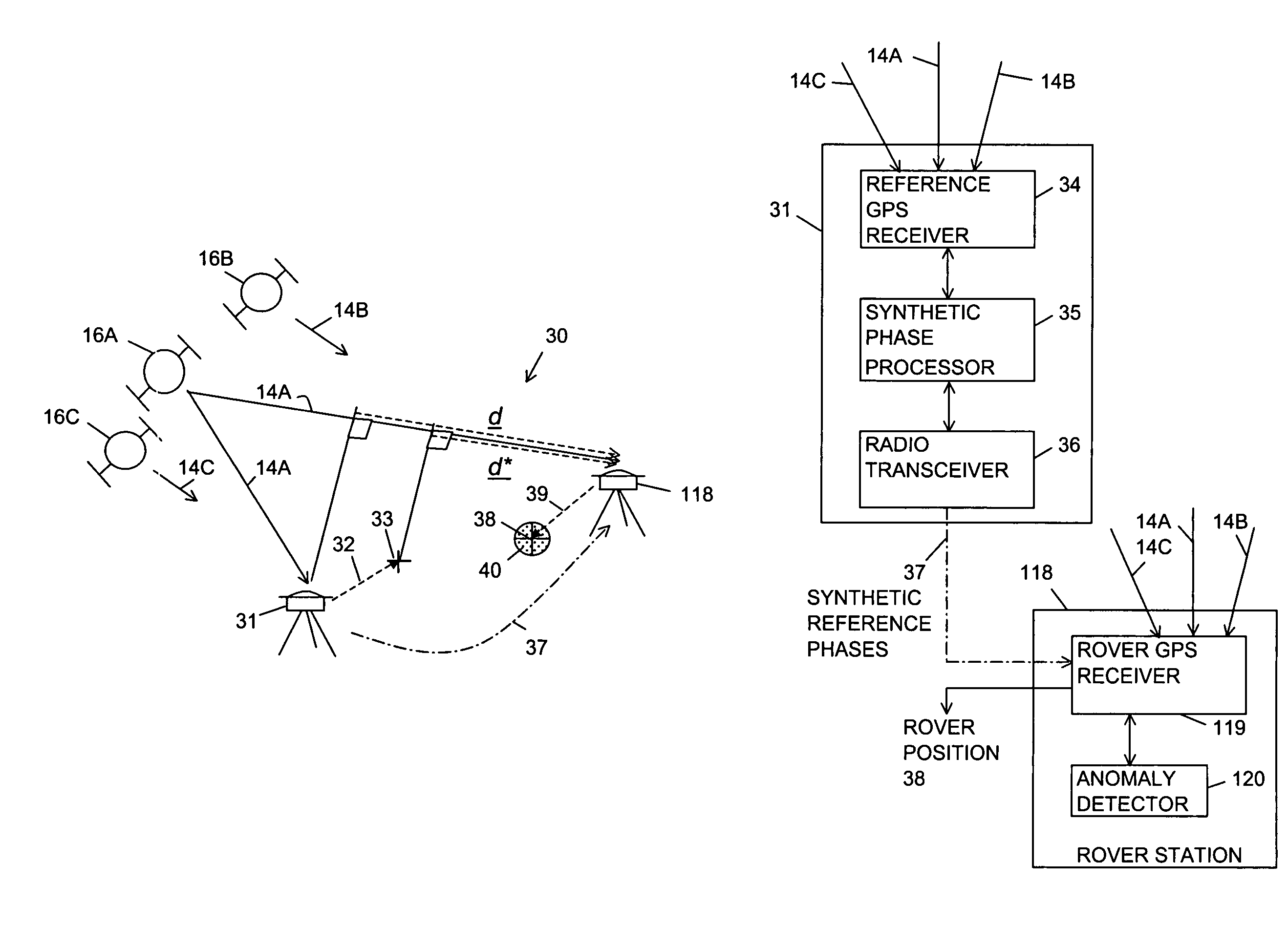
[0042]FIG. 2 is a diagram showing a real time kinematic (RTK) GPS-based positioning system of the present invention referred to with a reference number 30. The positioning system 30 includes at least one reference station 31 for receiving the GPS signals 14 from the GPS satellites 16. The reference station 31 has a reference position that is established by a survey or some other means. The system 30 receives or generates a synthetic offset vector 32 for controlling the positioning accuracy that is provided by the system 30 for one or more RTK GPS rover stations 118. The reference position and the synthetic offset vector 32 define a synthetic position 33 where the synthetic position 33 is separated from the reference position by the synthetic offset vector 32. The length and direction of the synthetic offset vector 32 are arbitrary. However, it is normally a few meters or less.
[0043]FIG. 2A is a block diagram showing the reference station 31 and the rover station 118. The reference station 31 includes a reference GPS receiver 34, a synthetic phase processor 35 and a radio transceiver 36. The reference GPS receiver 34 and the synthetic phase processor 35 may be separate or combined into a single unit. The radio transceiver 36 may be a transmitter without a receiver if two-way transmission with the rover station 118 is not required. The reference GPS receiver 34 measures the carrier phases of the GPS signals 14. The processor 35 uses the synthetic offset vector 32 with the reference position for the station 31 and the three dimensional angles to the GPS satellites 16 for inferring the synthetic reference phases for the carrier phases that would be measured if the measurements were made at the synthetic position 33.
[0044]The radio transceiver 36 sends a radio signal 37 having synthesized reference data for the synthetic reference phases and the reference position to the rover station 118. Cellular or landline telephones may be used to provide or to augment the radio signal 37. The synthesized reference data still includes a correct geographical reference position of the reference station 31, as is conventional, but the phases for the GPS signals 14 are not the actual phases that are measured at the reference position but are instead the synthetic reference phases that are calculated from the measured reference phases, the actual reference position and the synthetic offset vector 32 (or synthetic position 33).
[0045]The rover station 118 includes a rover GPS receiver 119 and an anomaly detector 120. The rover GPS receiver 119 receives the GPS signals 14 and measures the carrier phases from the same GPS satellites 16 and computes the differences between the measured rover phases and the synthetic reference phases. Using the synthetic reference phases in place of the actual reference phases, it now arrives at estimated perpendicular distance vectors represented by the vector d* instead of the estimated perpendicular distance vectors represented by the vector d described above. The vector d* may be understood as a dot product of the vector between the GPS satelite 16A and the rover station 118 and the vector between the synthetic position 33 and the rover station 118. When the rover station 118 calculates its position with respect to the reference station 31, it arrives at a position 38 that has an added positional error 39 of equal length in the opposite direction as the synthetic offset vector 32. Using this technique the positioning system 30 is able to arbitrarily introduce the added error 39 into the position 38 that is calculated by the rover station 118.
[0046]The rover GPS receiver 119 determines double difference phase residuals from current and previous synthetic reference phases and current and previous measured rover phases and passes the phase residuals to the anomaly detector 120. The anomaly detector 120 detects a phase residual anomaly when the phase residual is greater than a phase threshold corresponding to a selected distance for an integrity limit 40 for RTK operation. The integrity limit 40 corresponds to an outer limit of a zone about the rover position 38. When an anomaly is detected, the anomaly detector 120 inhibits the rover GPS receiver 119 from providing the rover position 38 to the user of the rover station 118, or provides a notification to the user that the anomaly was detected and allows the user to decide whether or not to use the position 38. Alternatively, the anomaly detector 120 provides a solution for the rover position 38 where the synthetic reference phase and measured rover phase for the particular GPS signal 14 associated with the anomaly are not used. The effect of the system 30 of the present invention is that the rover position 38 has the controlled added position error 39 without degrading the integrity limit 40 of the RTK positioning solution of the rover position 38.
[0047]FIG. 3 is a diagram showing a network embodiment of a real time kinematic (RTK) GPS-based positioning system of the present invention referred to by a reference number 50. The positioning system 50 includes a network of reference stations, referred to as 51A, 51B through 51N, for receiving the GPS signals 14 from the GPS satelites 16. The reference network stations 51A-N have reference positions established by a survey or some other means. The system 50 receives or generates a synthetic offset vector 32 for controlling the positioning accuracy that is provided by the system 50 for one or more RTK GPS rover stations shown as a rover station 124A, 124B or 124C. The rover station 124A, 124B or 124C includes a rover GPS receiver 125A, 125B or 125C, respectively, and an anomaly detector 126A, 126B or 126C, respectively.
[0048]The positioning system 50 also includes a server 52A, 52B or 52C. The server 52A-C and the reference network stations 51A-N communicate with radio signals 54. One of the network stations, for example the station 51A, may be designed as a master and the other reference network stations 51B-N as auxiliaries. The master reference station 51A and the server 52A-C may be co-located and may or may not share processing power; or the master reference station 51A and the server 52A-C may be physically separated.
[0049]The reference network stations 51A-N measure carrier phases of the GPS signals 14 and then communicate their phase measurements to the server 52A-C. The server 52A-C communicates with the rover station 124A-C with a radio signal 56. In a conventional system, the server 23 uses the virtual vector 27 and the master and auxiliary reference positions and phases for determining the virtual reference phases for the virtual reference position 26. In the present invention, the sum of the virtual vector 27 and the synthetic offset vector 32 is a master synthetic vector 64. The position of the master reference station 51A and the master synthetic vector 64 define a synthetic position 133. The system 50 of the present invention uses the synthetic offset vector 32 and the virtual vector 27 (or the master synthetic vector 64) and the master and auxiliary reference positions and phases for determining the synthetic reference phases for the synthetic position 133.
[0050]The rover station 124A-C expects reference phases as if the phases are measured at the virtual reference position 26, however, it receives the synthetic reference phases inferred for the synthetic position 133. The rover GPS receiver 125A-C receives the GPS signals 14 and measures the carrier phases from the same GPS satellites 16; and computes the differences between the measured rover phases and the synthetic reference phases. Using the synthetic reference phases in place of the virtual reference phases, it now arrives at estimated perpendicular distance vectors represented by the vector d* describe above. When the rover station 124A-C calculates its position with respect to the virtual position 26, it arrives at the position 38 relative to the virtual reference position 26 that has the added positional error 39 that is equal in length and in the opposite direction as the synthetic offset vector 32. Using this technique the positioning system 50 is able to arbitrarily introduce the added error 39 into the position 38 that is calculated by the rover station 124A-C.
[0051]The server 52A-C and the rover station 124A-C may use two-way communication to agree on the geographical position for the virtual reference position 26. For example, the virtual reference position 26 may be selected to be the best estimated position of the rover station 124A-C. It should be noted that the invention is not dependent on the location of the processing power of the server 52A-C. The processing power of the server 52A-C may be located anywhere within communication range and may be distributed in several locations. Cellular or landline telephones may be used to provide or to augment the radio signals 54 and / or 56.
[0052]FIG. 3A is a block diagram of the server 52A. The server 52A includes a radio transceiver 62, a virtual reference synthetic phase processor 63 and an anomaly detector 63A. The server 52A receives data for the reference positions (or it already has the reference positions) and the reference phases from the reference stations 51A-N. The processor 63 uses a virtual reference system (VRS) parametric model with the master synthetic vector 64A (in place of the virtual vector 27) together with the master and auxiliary reference network positions and phases for the reference network stations 51A-N and the three dimensional angles to the GPS satellites 16 for inferring the synthetic reference phases that would be measured if the measurements were made at the synthetic position 133 (instead of the virtual reference position 26).
[0053]The radio transceiver 62 transmits the radio signal 56 having synthesized reference data to the rover station 124A. The synthesized reference data still includes a correct geographical virtual reference position 26, as is conventional, but includes the synthetic reference phases in place of the actual or virtual reference phases that are used by a conventional rover station for positioning operation without the accuracy control of the present invention.
[0054]FIG. 3B is a block diagram of the server 52B. The server 52B includes the radio transceiver 62, a synthetic phase processor 65, a virtual reference processor 66 and an anomaly detector 66A. The server 52B receives data for the reference positions (or it already has the reference positions) and the reference phases from the reference stations 51A-N. The virtual reference processor 66 uses the virtual vector 27 and the reference positions and phases for the reference stations 51A-N with the three dimensional angles to the GPS satellites 16 for determining the virtual reference phases. The virtual reference processor 66 then passes the virtual reference phases and the virtual reference position 26 to the synthetic phase processor 65.
[0055]The synthetic phase processor 65 uses the synthetic offset vector 32 with the virtual reference phases and the three dimensional angles to the GPS satellites 16 for inferring the synthetic reference phases for the carrier phases that would be measured if the measurements were made at the synthetic position 133. The radio transceiver 62 transmits the radio signal 56 having synthesized reference data to the rover station 124B. The synthesized reference data still includes a correct geographical virtual reference position 26, as is conventional, but the phases for the GPS signals 14 are not the virtual reference phases that would be measured at the virtual reference position 26 but are instead synthetic reference phases that would be measured at the synthetic position 133.
[0056]FIG. 3C is a block diagram of the server 52C. The synthetic phase processor 65 is located separately from the virtual reference processor 66. The server 52C uses the public switch telephone network (PTSN) telephone system 68 for receiving reference data and uses the telephone system 68 for communication between the virtual reference processor 66 and the synthetic phase processor 65. The processor 65 receives data for the virtual reference position 26 and virtual reference phases from the virtual reference processor 66 and then infers the synthetic reference phases as described above. The processor 65 may be located adjacent to the rover station 124C having a local wired connection or a cellular telephone 69 may be used to pass the synthetic reference phases to the rover station 124C.
[0057]The virtual reference processors 63 and 66 determine double difference phase residuals between the master and auxiliary phases for current and previous phase measurements and pass the phase residuals to the respective anomaly detectors 63A and 66A. The anomaly detector 63A and 66A detects a phase residual anomaly when the phase residual is greater than a phase threshold corresponding to a selected distance or integrity limit 40 for RTK operation. The virtual reference processors 63 and the anomaly detectors 63A and 66A, respectively, may share hardware and software.
[0058]The rover GPS receivers 125A-C also determine double difference phase residuals. The phase residuals determined in the rover GPS receivers are the differences between the rover phases and the synthetic reference phases for current and previous phase measurements. The, rover GPS receivers 125A-C pass the phase residuals to the respective anomaly detectors 126A-C. The anomaly detectors 126A-C also detect a phase residual anomaly when the phase residual is greater than a phase threshold corresponding to a selected distance or integrity limit 40 for RTK operation. The rover GPS receiver 125A-C and the anomaly detector 126A-C, respectively, may share hardware and software.
[0059]The integrity limit 40 corresponds to a zone about the rover position 38. When an anomaly is detected, the anomaly detector 63A, 66A or 126A-C inhibits the rover GPS receiver 125A-C from providing the rover position 38 to the user of the rover station 124A-C, or provides a notice to the user that the anomaly was detected and allows the user to decide whether or not to use the position 38. Alternatively, the rover station 124A-C provides a solution for the rover position 38 where the synthetic reference phase and measured rover phase for the particular GPS signal 14 associated with the anomaly are not used. The effect of the system 50 of the present invention is that the rover position 38 has the controlled added position error 39 without degrading the integrity limit 40 of the RTK positioning solution for the rover position 38.
[0060]In the system 50, it may be beneficial to reduce the amount of data that is transmitted among various locations by sending differences between master and auxiliary reference network positions and / or reference network phases in place of the actual reference positions and phases. For example, the reference positions and phases for the auxiliary stations 51B-N may be transmitted as differences with respect to the reference position and phases the master reference station 51A.
[0061]FIG. 4 is a diagram showing a secure real time kinematic (RTK) GPS rover station 70 of the present invention for receiving conventional reference data in a secure format from a GPS-based positioning system 71. The positioning system 71 includes at least one reference station 112 having a reference position that is established by a survey or some other means for receiving GPS signals 14 from GPS satellites 16. The reference station 112 measures the carrier phases of the GPS signals 14 and sends a radio signal 117 having secure reference data for the reference phases to the rover station 70. The security of the reference data may be maintained by the measures of the Digital Millennium Copyright Act of 1998 for preventing unauthorized access to a copyrighted work. Alternatively, the reference data may be encrypted.
[0062]The rover station 70 receives or generates or otherwise selects the synthetic offset vector 32. The synthetic offset vector 32 and the reference position of the reference station 112 define a synthetic position 33 as described above. The length and direction of the synthetic offset vector 32 is arbitrary but the length is normally a few meters or less. When it is desired for the rover station 70 of the present invention to operate with existing RTK GPS-based reference systems, the reference station 112 may be a conventional reference station 12 described above with the addition of security measures for protecting the reference data from unauthorized access.
[0063]FIG. 4A is a block diagram of the rover station 70. The rover station 70 includes an RTK rover GPS receiver 74 including an anomaly detector 74A, a secure synthetic phase processor 75, and a radio transceiver 76. The rover GPS receiver 74 measures the carrier phases for the same GPS signals 14 that are measured by the reference station 112. The radio transceiver 76 may be replaced by a radio receiver without a transmitter if two-way communication is not required. A cellular telephone may be used for the radio transceiver 76. The radio transceiver 76 receives the reference position and the secure reference data for the reference phases in the radio signal 117.
[0064]The secure synthetic phase processor 75 selects the synthetic offset vector 32 and then uses the synthetic offset vector 32 with the reference position, the secure reference phases and the three dimensional angles to the GPS satellites for inferring the synthetic reference phases. The secure synthetic phase processor 75 performs processing on signals and data within physical boundaries of the processor 75 in a way that makes it difficult for an authorized user to alter the processing algorithms or view the signals or data. Further, the algorithms, signals, messages and data are protected by the access controls of the Digital Millennium Copyright Act of 1998.
[0065]The secure synthetic phase processor 75 passes the synthetic reference phases to the rover GPS receiver 74. The GPS receiver 74 uses the synthetic reference phases and the measured rover phases with the reference position and the three dimensional angles to the GPS satellites 16 to compute the rover position 38. The conventional rover station 18 would calculate the difference between the reference and rover phase measurements for the distance vectors represented by the vector d to the GPS satellite 16A. However, the rover station 70 of the present invention arrives at estimated perpendicular distance vectors represented by d* instead of the vectors represented by d.
[0065]The secure synthetic phase processor 75 passes the synthetic reference phases to the rover GPS receiver 74. The GPS receiver 74 uses the synthetic reference phases and the measured rover phases with the reference position and the three dimensional angles to the GPS satellites 16 to compute the rover position 38. The conventional rover station 18 would calculate the difference between the reference and rover phase measurements for the distance vectors represented by the vector d to the GPS satellite 16A. However, the rover station 70 of the present invention arrives at estimated perpendicular distance vectors represented by d* instead of the vectors represented by d.
[0066]When the rover station 70 calculates its position with respect to the reference station 112, it arrives at a position 38 that has a vector position offset error 39 of equal length and in the opposite direction as the synthetic offset vector 32. The security measures in the secure processor 75 prevent the user from undoing the accuracy control of the present invention by using the measured reference phases instead of the synthetic reference phases. Measurements by the rover GPS receiver 74 from several GPS satellites 16 yield several perpendicular distance vectors d* and ultimately the position of the rover station 70 with respect to the reference station 112 with the added error 39. Using this technique the secure synthetic phase processor 75 is able to introduce the arbitrary added error 39 into the position 38 that is calculated by the rover station 70. The rover GPS receiver 74 determines phase residuals from current and previous synthetic reference phases and measured rover phases and passes the phase residuals to the anomaly detector 74A. The anomaly detector 74A detects a phase residual anomaly when the phase residual is greater than a phase threshold corresponding to a selected integrity limit 40 for RTK operation. The integrity limit 40 corresponds to a zone about the rover position 38. When an anomaly is detected, the anomaly detector 74A inhibits the rover GPS receiver 74 from providing the rover position 38 to the user of the rover station 70, or provides a notification to the user that the anomaly was detected and allows the user to decide whether or not to use the position 38. Alternatively, the anomaly detector 74A provides a solution for the rover position 38 where the synthetic reference phase and measured rover phase for the particular GPS signal 14 associated with the anomaly are not used. The effect of the system 70 of the present invention is that the rover position 38 has the controlled added position error 39 without degrading the integrity limit 40 of the RTK positioning solution for rover position 38.
[0067]FIG. 5 is a diagram showing a secure real time kinematic (RTK) GPS rover station 80A or 80B of the present invention for receiving conventional reference data in a secure format from a network positioning system 81. The rover station 80A-B receives reference data having secure reference phases from the system 81 and selects the synthetic offset vector 32 for controlling the positioning accuracy that it provides. The security of the reference phases may be protected by the access control measures of the Digital Millennium Copyright Act of 1998 and / or by encryption. The positioning system 81 includes a server 123 and a network of reference network stations, referred to as 112A, 112B through 112N, having reference positions that are known from a survey or other means.
[0068]The reference network satelite 112A-N include reference GPS receivers for receiving the GPS signals 14 from the GPS satellites 16 and measuring carrier phases. When it is desired for the rover station 80A-B of the present invention to operate with existing RTK GPS-based reference systems, the reference stations 112A-N may be conventional reference stations 12A-N and the server 123 may be the conventional serve 23 described above with the addition of security measures for protecting the reference data. One of the reference stations, illustrated as 112A, may be designated as a master reference station and the other reference network stations 112B-N as auxiliaries.
[0069]The reference network stations 112A-N communicate with the server 123 in signals 122 and the server communicates with the rover station 80A-B with a radio signal 127 having a secure data format so that the reference phases cannot easily be used by an unauthorized user. The sum of the virtual vector 27 and the synthetic offset vector 32 is a master synthetic vector 64. The position of the master reference station 112A and the master synthetic vector 64 define a synthetic position 133.
[0070]FIG. 5A is a block diagram of the rover station 80A. The rover station 80A includes a radio transceiver 82, a secure virtual reference synthetic phase processor 83 and an RTK rover GPS receiver 84A including an anomaly detector 86A. The radio transceiver 82 receives data for the master and auxiliary reference positions and phases for the master and auxiliary reference network stations 112A-N in the radio signal 127. The radio transceiver 82 may be a radio receiver without a transmitter if two-way communication is not required. The radio transceiver 82 may be a cellular telephone. In order to reduce the amount of data that is transmitted, the reference positions and phases for the auxiliary reference stations 112B-N may be transmitted as differences from the reference position and phases of the master reference station 112A.
[0071]The synthetic phase processor 83 receives or generates or otherwise selects the synthetic offset vector 32 and then determines the virtual reference position 26, or negotiates with the server 123 to determine the virtual reference position 26. The virtual reference position 26 and the synthetic offset vector 32 define the synthetic position 133 where the synthetic position 133 is separated from the virtual reference position 26 by the synthetic offset vector 32. The processor 83 determines the master synthetic vector 64 from the vector sum of the virtual vector 27 and the synthetic offset vector 32 (or the virtual reference position 26 and the synthetic offset vector 32). The length and direction of the synthetic offset vector 32 are arbitrary but the length is normally a few meters or less.
[0072]The processor 83 then uses the master synthetic vector 64, in place of the virtual vector 27, together with the master and auxiliary reference network positions and phases for the reference network stations 112A-N and the three dimensional angles to the GPS satellites 16 for inferring the synthetic reference phases that would be measured if the measurements were made at the synthetic position 133. The processor 83 passes the synthetic reference data for the virtual reference position 26 and the synthetic reference phases to the rover GPS receiver 84A. The rover GPS receiver 84A measures the phases of the same GPS signals and uses the measured rover phases, the master and auxiliary reference positions and phases with the synthetic reference phases and the virtual reference position 26 for determining the rover position 38.
[0073]FIG. 5B is a block diagram of the rover station 80B. The rover station 80B is similar to the rover station 70 described above with the exception that the rover station 80B uses the virtual reference position 26 in place of the actual reference position of the reference station 112. The rover station 80B includes a radio transceiver 82, the rover GPS receiver 84B including an anomaly detector 86B, and a secure synthetic phase processor 85. The radio transceiver 82 receives data for the virtual reference position 26 and the virtual reference phases in the radio signal 127.
[0074]The processor 85 uses the synthetic offset vector 32 (or the difference between the virtual reference position 26 and the synthetic position 133) with the virtual reference position 26, virtual reference phases and the three dimensional angles to the GPS satellites for inferring the synthetic reference phases that would be measured at the synthetic position 133. The processor 85 passes the synthetic reference data for the virtual reference position 26 and the synthetic reference phases to the rover GPS receiver 84B. The rover GPS receiver 84B measures the phases of the same GPS signals and uses the measured rover phases with the synthetic reference phases and the virtual reference position 26 for determining the rover position 38.
[0075]The rover GPS receiver 84A-B determines phase residuals from current and previous synthetic reference phases and measured rover phases and passes the phase residuals to the anomaly detector 86A-B. The anomaly detector 86A-B detects a phase residual anomaly when the phase residual is greater than a phase threshold corresponding to a selected distance or integrity limit 40 for RTK operation. The integrity limit 40 corresponds to a zone about the rover position 38. When an anomaly is detected, the anomaly detector 86A-B inhibits the rover GPS receiver 84A-B from providing the rover position 38 to the user of the rover station 80A-B, or provides a notification to the user that the anomaly was detected and allows the user to decide whether or not to use the position 38. Alternatively, the anomaly detector 86A-B provides a solution for the rover position 38 where the synthetic reference phase and measured rover phase for the particular GPS signal 14 associated with the anomaly are not used.
[0076]The position 38 calculated by the rover station 80A-B relative to the virtual reference position 26 has the added positional offset error 39 that is equal in length and in the opposite direction as the synthetic offset vector 32. Using this technique the rover station 80A-B is able to arbitrarily introduce the added error 39 into the position 38 without degrading the integrity limit 40 of the RTK positioning solution for the rover position 38.
[0077]The secure synthetic phase processors 83 and 85 perform processing on signals and data that are embedded with the boundaries of the rover stations 80A and 80B in a way that makes it physically difficult for users of the rover stations 80A and 80B to alter the processing algorithms or view the signals or data. Further, the algorithms, signals, messages and data are protected by the access controls of the Digital Millennium Copyright Act of 1998.
[0078]FIGS. 6A and 6B are block diagrams of random reference generators of the present invention referred to by reference numbers 90A and 90B, respectively. The random reference generator 90A is used in the synthetic phase processors 63 and 83 of the present invention with a VRS parametric model for generating synthetic reference phases. The random reference generator 90B is used in the synthetic phase processors 35, 65, 75 and 85 of the present invention with an actual or virtual reference position for generating synthetic reference phases. The synthetic reference phases are passed from the systems 30 and 50 to the RTK GPS receivers in the rover stations 118 or 124A-C for determining the rover position 38; or computed in secure processors within the rover station 70 or 80A-B for determining the rover position 38.
[0079]The random reference generators 90A and 90B include a random process vector generator 170. The random process vector generator 170 stores or receives values for a maximum rate of change and one or more maximum dimensions and uses the values as inputs to a random or pseudo-random process for continuously computing synthetic offset vectors 32. Importantly, because the synthetic offset vectors 32 are computed with a random or nearly random process, the added error 39 is not easily reversible by users or software programming in the rover stations.
[0080]The value or values for maximum dimensions may be a maximum radius for providing a spherical error zone, a maximum radius and a maximum length for providing a cylindrical error zone, three maximum lengths X, Y and Z for providing a box error zone, or the like. The error zones refer to a volume or a three dimensional range of the added error 39 for the rover position 38 about the position for the rover station that would be determined by an RTK rover station without the present invention for accuracy control. For example, the added offset 39 for the box error zone has possible errors x, y and z in three dimensions of |x|≦X, |y|≦Y and |z|≦Z. The box error zone need not have equal or orthogonal dimensions. The values for the maximum dimensions z=0 or x and y=0 may be used to constrain the random process vector generator 170 so that the added error 39 is confined to horizontal or vertical directions, respectively.
[0081]The added error 39 may be of relatively large magnitude but low rate of change in any direction while the rover GPS receiver, constructed for fixed RTK operation, continues to use the resolved integer number of carrier phase cycles for its positioning. By continuing to use the integers, the rover position 38 has the integrity of the RTK GPS solution within the integrity limit 40 as small as a few centimeters even when the added error 39 is a few meters or more. The RTK rover position 38 has high integrity even when the accuracy is degraded with the present invention because the errors due to multipath are largely eliminated. It will be appreciated by those skilled in the art that merely dithering the reference carrier phase measurements directly and providing the dithered reference phases to the rover station may make it impossible for an RTK rover station to resolve the carrier phase integer, thereby losing the benefit of the high integrity of the RTK position solution.

