
Image data acquisition optimisation

a technology of image data and acquisition optimization, applied in the direction of static indicating devices, instruments, editing/combining figures or texts, etc., can solve the problems of resolution, complexity, and unsatisfactory rips, and achieve the effect of reducing the number of rips

Inactive Publication Date: 2007-11-06
CANON KK
View PDF6 Cites 24 Cited by
  • Summary
  • Abstract
  • Description
  • Claims
  • Application Information

AI Technical Summary

Benefits of technology

[0010]It is an object of the present invention to substantially overcome,

Problems solved by technology

A number of these factors are outside the control of the RIP (e.g. rendering resolution, complexity).
However, no RIP is ideal.
The performance of most RIPs is compromised by redundant or repetitive processing of data.
This often involves much unnecessary work since objects with irregular boundary outlines must first be padded with transparent pixels out to their bounding boxes, after which the padded pixels have to undergo the fall compositing operation.

Method used


Image

  • Image data acquisition optimisation
  • Image data acquisition optimisation
  • Image data acquisition optimisation

Examples


Embodiment Construction

[0161]Where reference is made in any one or more of the accompanying drawings to steps and / or features, which have the same reference numerals, those steps and / or features have for the purposes of this description the same function(s) or operation(s), unless the contrary intention appears.

1.0 General Overview

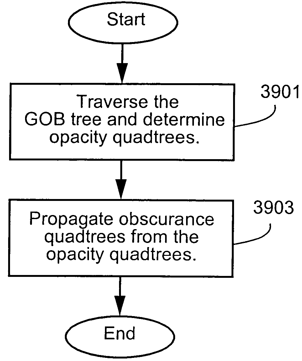
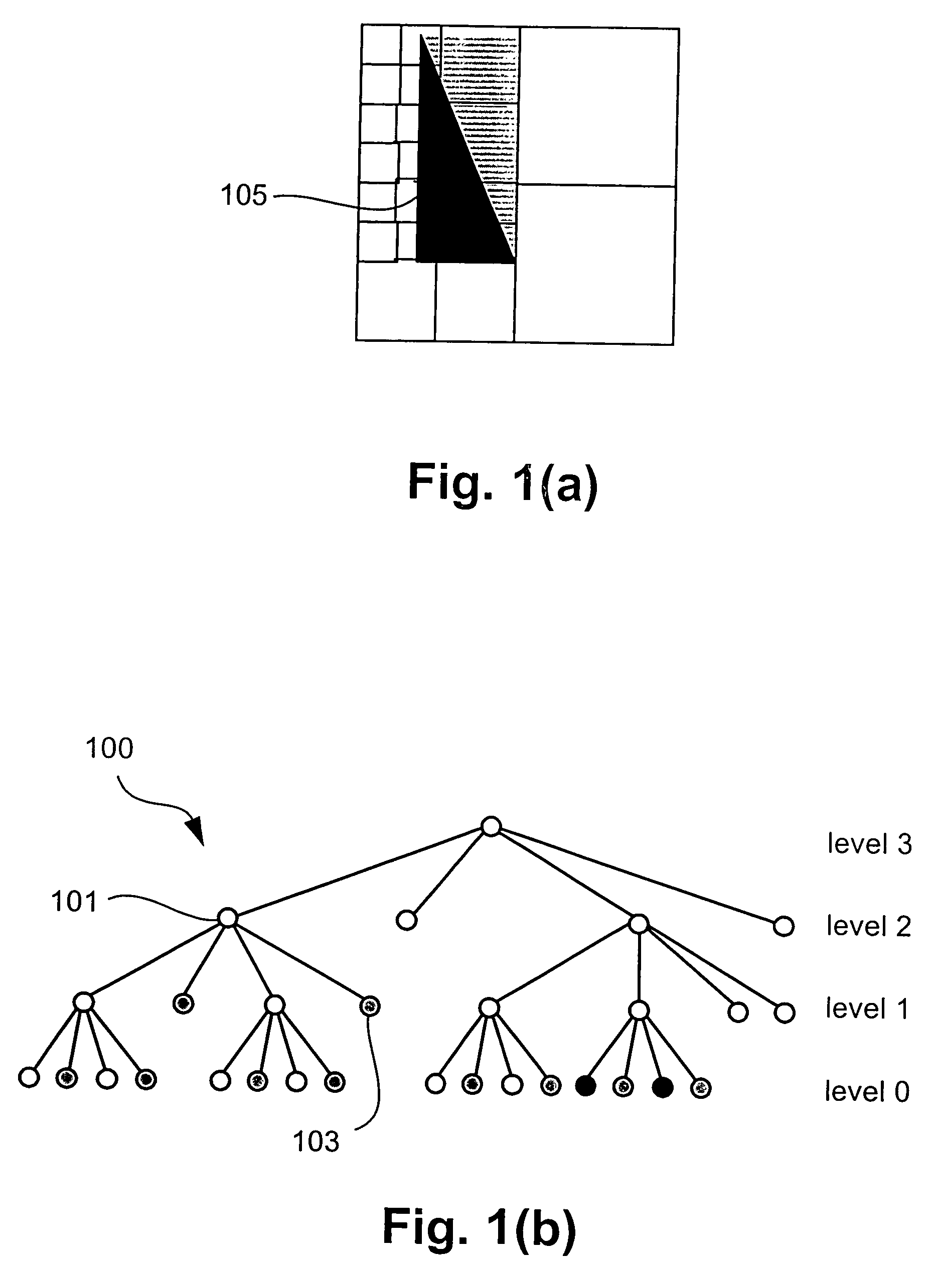
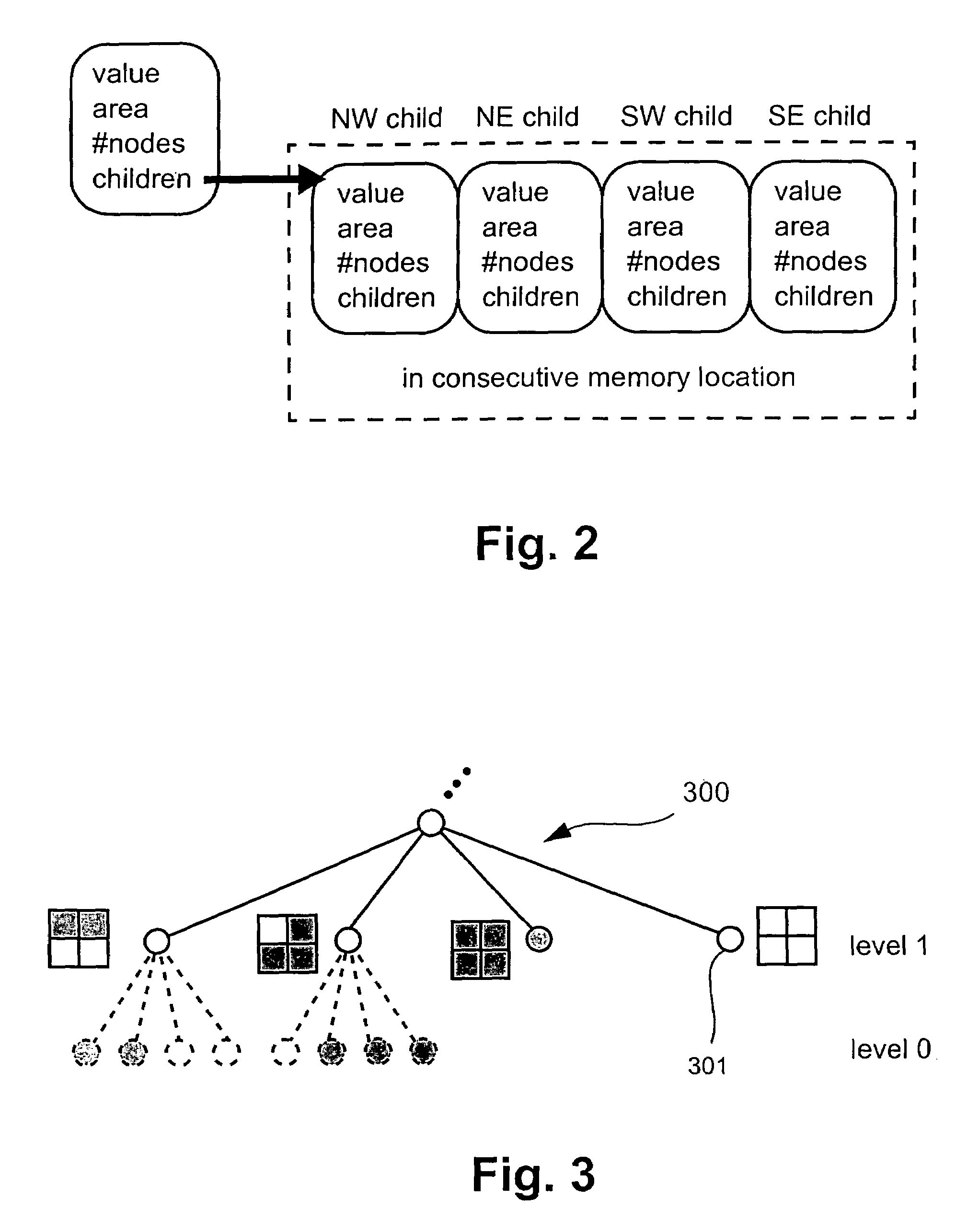
[0162]A method of rendering an image is described below. The image is formed by rendering graphical objects according to a hierarchical GOB tree which represents a compositing expression for the image, whereby each of the graphical objects of the GOB tree has a predetermined boundary outline. The method uses quadtrees (referred to as “obscurance” quadtrees), which are stored at each leaf node of a GOB tree, to perform obscurance analysis on the graphical objects of the GOB tree. The obscurance analysis results in an optimisation of the amount of data processed during the rendering of the image represented by the GOB tree, by excluding the obscured regions of objects. A method fo...


PUM


Abstract

A method of creating an image is disclosed. The image is formed by rendering at least a plurality of graphical objects to be composited according to a first hierarchical structure (eg. 4500) representing a compositing expression for the image. The first hierarchical structure (4500) includes a plurality of nodes each representing at least a component of the image or an operation for combining sub-expressions of the compositing expression. The method stores a second hierarchical structure (300) for at least one node of the first hierarchical structure (4500). The second hierarchical structure (300) indicates at least an unobscured region of an object associated with the node. A space in which the object is defined is partitioned into a plurality of regions. The second hierarchical structure (300) is then overlayed on the object such that the object is substantially encompassed within the second hierarchical structure (300) and the overlayed second hierarchical structure (300) is traversed to identify any of the plurality of regions which include at least a portion of the unobscured region. Finally, the image is created by rendering the identified regions.

Description

TECHNICAL FIELD OF THE INVENTION[0001]The present invention relates generally to the creation of computer-generated images and, in particular, to a method and apparatus for creating an image formed by compositing multiple components. The invention also relates to a computer program product including a computer readable medium having recorded thereon a computer program for apparatus for creating an image made up by compositing multiple components.BACKGROUND ART[0002]Computer generated images are typically made up of many differing components or graphical objects which are rendered and composited together to create a final image. In recent times, an “opacity channel” (also known as a “matte”, an “alpha channel”, or simply “opacity”) has been commonly used. The opacity channel contains information regarding the transparent nature of each object. The opacity channel is stored alongside each instance of a colour, so that, for example, a pixel-based image with opacity stores an opacity va...

Claims


Application Information

Patent Timeline
IPC IPC(8): G09G5/00G06K9/36G06K9/46G06T11/20G09G5/10G06T3/00G06T11/60G06T17/00H04N1/387
CPCG06T17/005G06T11/60
Inventor DOAN, KHANH PHI VANCOMBES, IAN GEOFFREY
Owner CANON KK
Learn More