Eureka AIR delivers breakthrough ideas for toughest innovation challenges, trusted by R&D personnel around the world.

Highly pipelined printing system architecture

a printing system and pipeline technology, applied in the field of high-performance print systems, can solve the problems of reducing engine throughput, difficult to provide a continuous supply of raw print data to the printer engine as required, and the printing system to operate below the maximum performance level

Inactive Publication Date: 2005-10-11
CANON KK
View PDF17 Cites 13 Cited by
  • Summary
  • Abstract
  • Description
  • Claims
  • Application Information

AI Technical Summary

Benefits of technology

[0006]It is an object of the present invention to substantially overcome, or at least ameliorate, one or more disadvantages of existing arrangements.

Problems solved by technology

This cycle down / cycle up process reduces engine throughput considerably, and of course, causes the printing system to operate below maximum performance levels.
The presence of bottlenecks which are inherent in conventional sequential printing systems makes it difficult to provide a continuous supply of raw print data to the printer engine as required.
As printer engine speeds increase, this problem is exacerbated, since the speed with which the raw data must be supplied to the print engine also increases.
The aforementioned technological advances place increasing strain on the conventional sequential processing model.
This approach can sometimes eliminate the cycle down / cycle up problem if applied to a relatively short print run.
A penalty is incurred, however, since spooling adds additional overhead to the print data processing, because data must be typically copied to, and from, a relatively slow storage device such as a hard disc.
Furthermore, the spooling approach also introduces additional start-up delay, before the first page of a job can be printed.

Method used


Image

  • Highly pipelined printing system architecture
  • Highly pipelined printing system architecture
  • Highly pipelined printing system architecture

Examples


Embodiment Construction

[0042]Where reference is made in any one or more of the accompanying drawings to steps and / or features, which have the same reference numerals, those steps and / or features have for the purposes of this description, the same function(s) or operation(s), unless the contrary intention appears.

[0043]In the context of this specification, the term “line” is used to denote a data connection between process blocks, and / or between sub-process blocks. Data connections can take a variety of different, but functionally equivalent physical forms, including hard-wired and wired connections, and can also represent software calls between software processes.

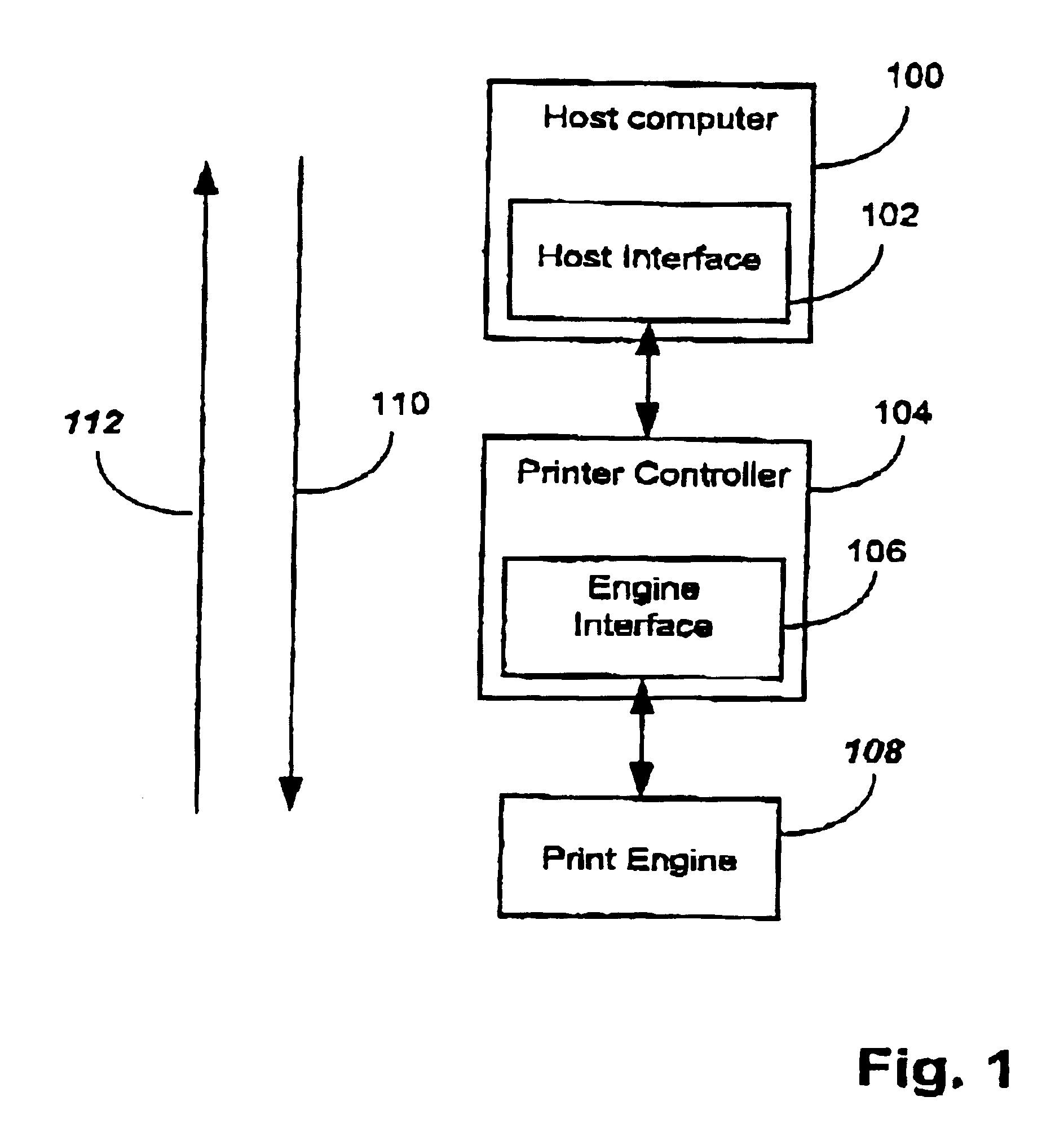
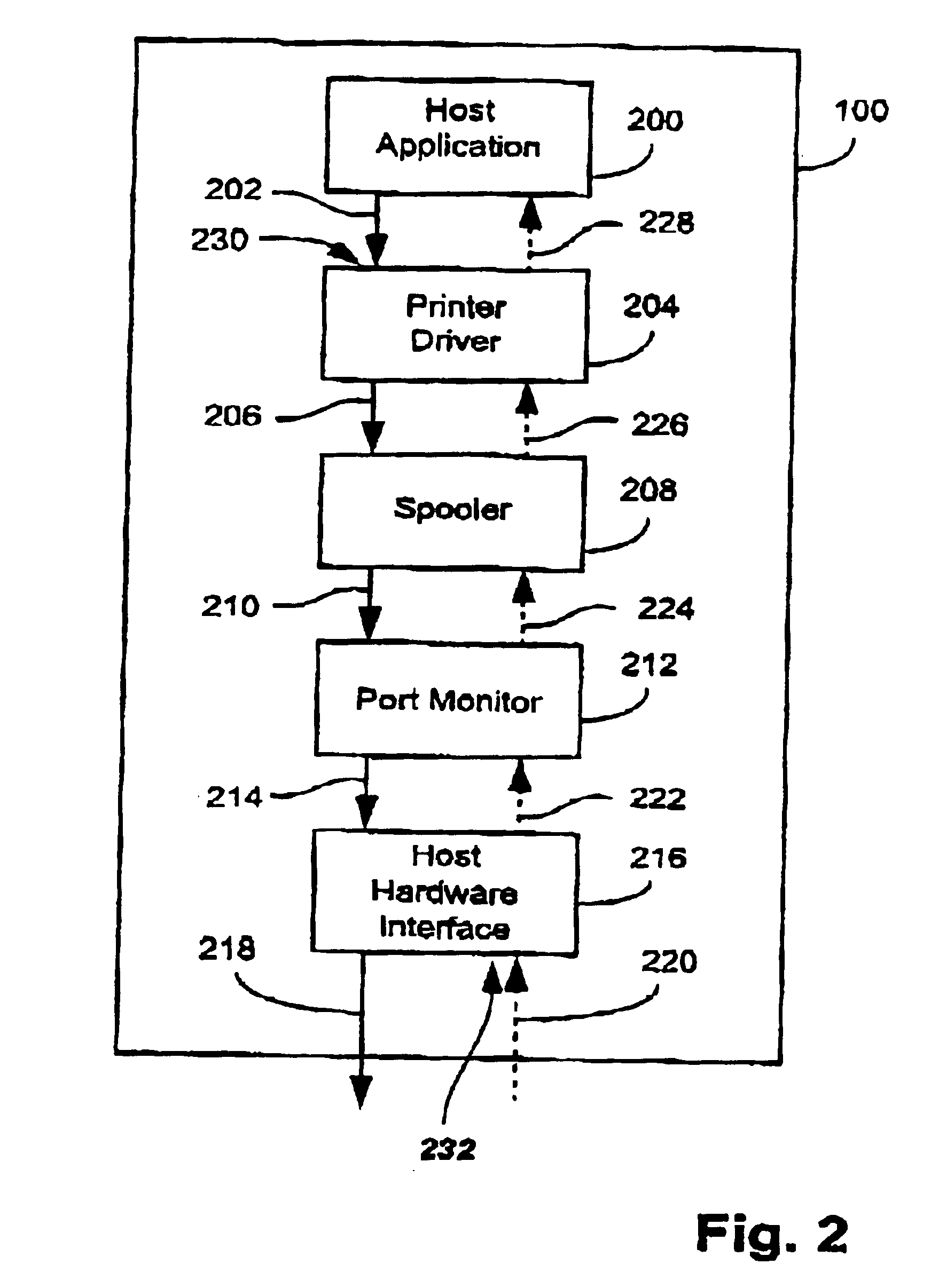
[0044]FIG. 1 shows major hardware components of a printing system, according to a first arrangement. The system supports both a forward data flow depicted by an arrow 110, and a reverse data flow depicted by an arrow 112. A host computer 100 incorporates a host interface 102, which provides an operative coupling between the host computer 100 and ...


PUM


Abstract

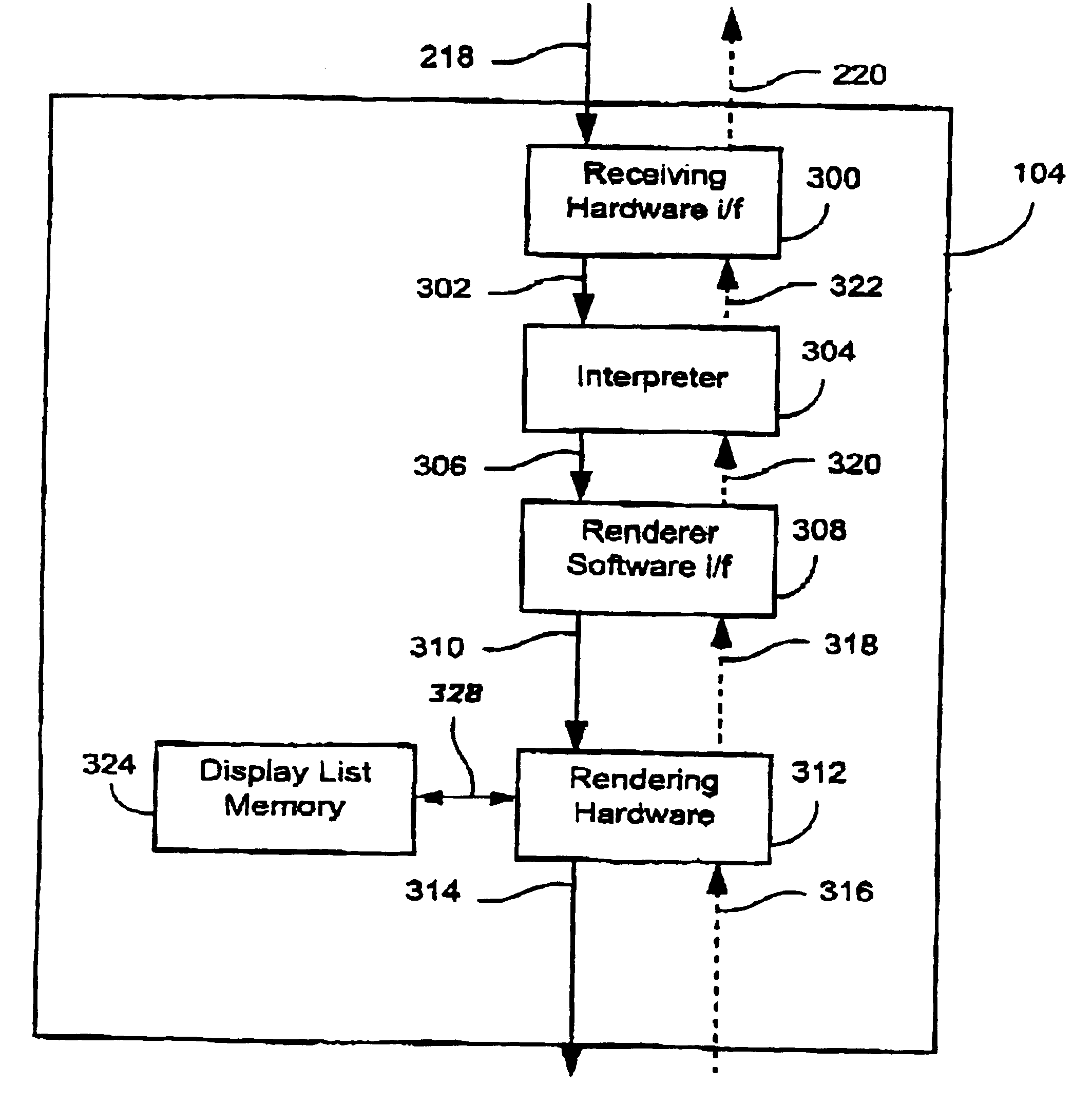
A printing system is disclosed, the system including a receiving hardware interface (300) for coupling page description data to an interpreter (304) said interpreter interpreting the page description data to thereby output a display list to a renderer software interface (308) which processes the display list to thereby output a processed display list, and rendering hardware (312) for processing the processed display list to thereby output raw pixel data, wherein the receiving hardware interface (300), the interpreter (304), the rendering software interface (308), and the rendering hardware (312) are arranged to operate in a pipelined manner, being thereby capable of concurrently processing job data from at least one page of the print job.

Description

TECHNICAL FIELD OF THE INVENTION[0001]The present invention relates generally to printing systems, and in particular, to high performance print systems. The present invention relates to a method and apparatus for pipeline data processing in printer systems.BACKGROUND ART[0002]Conventional desktop and mainframe computer-based printing systems typically operate by processing pages in a document in a sequential manner. Accordingly, each page is individually processed, the individual processing for a particular page having to be completed before processing for a following page commences. As a consequence, the processing for a page does not begin until the previous page has been completely printed. The printing process itself typically consists of a number of sequential processing stages, each of which is made up of a combination of computer software and hardware based sub-processes. In the conventional printing model, each sub-process stage must be fully completed before the next sub-pr...

Claims


Application Information

Patent Timeline
Patent Type & Authority Patents(United States)
IPC IPC(8): G06F3/12
CPCG06F3/1212G06F3/126G06F3/1285G06F3/1229
Inventor STONEY, GRAHAM
Owner CANON KK
Why Eureka
Eureka Blog
Learn More