
Electric leakage detection system

a detection system and electric leakage technology, applied in short-circuit testing, emergency protective arrangements for limiting excess voltage/current, instruments, etc., can solve the problem of inapplicability of the proposal described above, the inability to determine the position of the electric leakage, and the complexity of distributing the ground lin

Inactive Publication Date: 2007-11-13
KOKUSAN DENKI CO LTD
View PDF4 Cites 9 Cited by
  • Summary
  • Abstract
  • Description
  • Claims
  • Application Information

AI Technical Summary

Benefits of technology

Enables effective detection and positioning of electric leaks in AC generators without the need for long ground lines and neutral points, improving system reliability and flexibility.

Problems solved by technology

In such an electric leakage detection system for detecting an electric leakage from a zero-phase current flowing through a ground line which grounds a neutral point of a generator when the electric leakage occurs, it is necessary to lay around the long ground line which grounds the neutral point of the generator to a place of installation when it is required to install the electric leakage detection system apart from the generator, and thus complexity for distributing the ground line was a problem.
In addition, when there is not a neutral point among the armature coils of the AC generator, for example, a case where the armature coils are delta-connected or the generator is a single-phase AC generator, a proposal described above cannot be applied.
However, determination of a position of the electric leakage cannot be performed in a conventional electric leakage detection system.

Method used


Image

  • Electric leakage detection system
  • Electric leakage detection system
  • Electric leakage detection system

Examples


Embodiment Construction

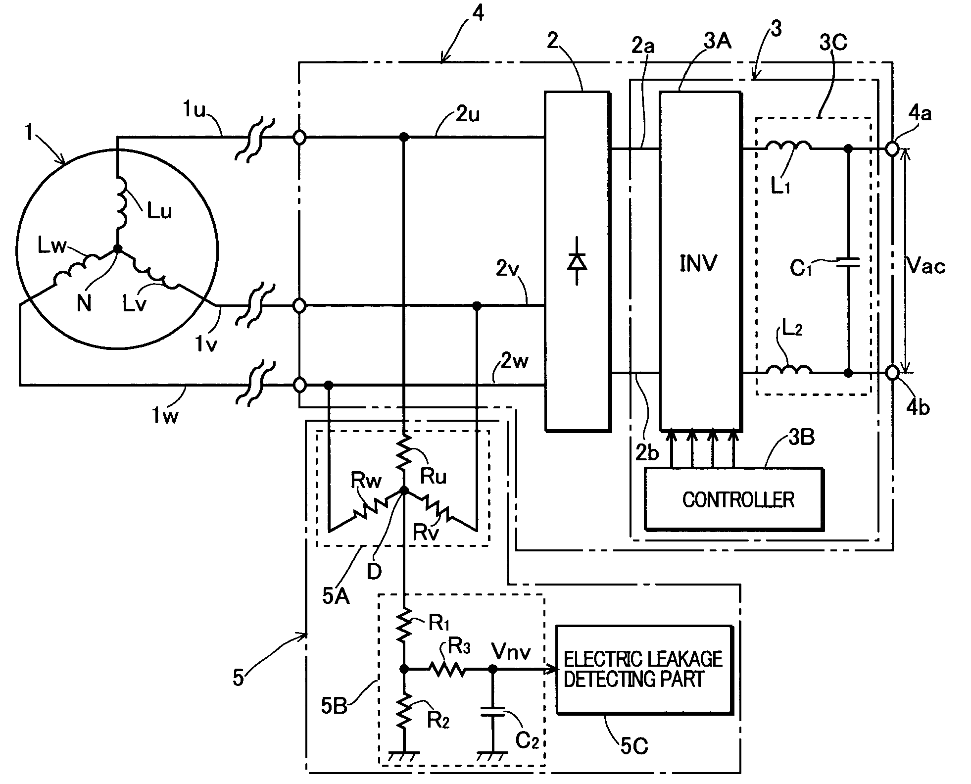
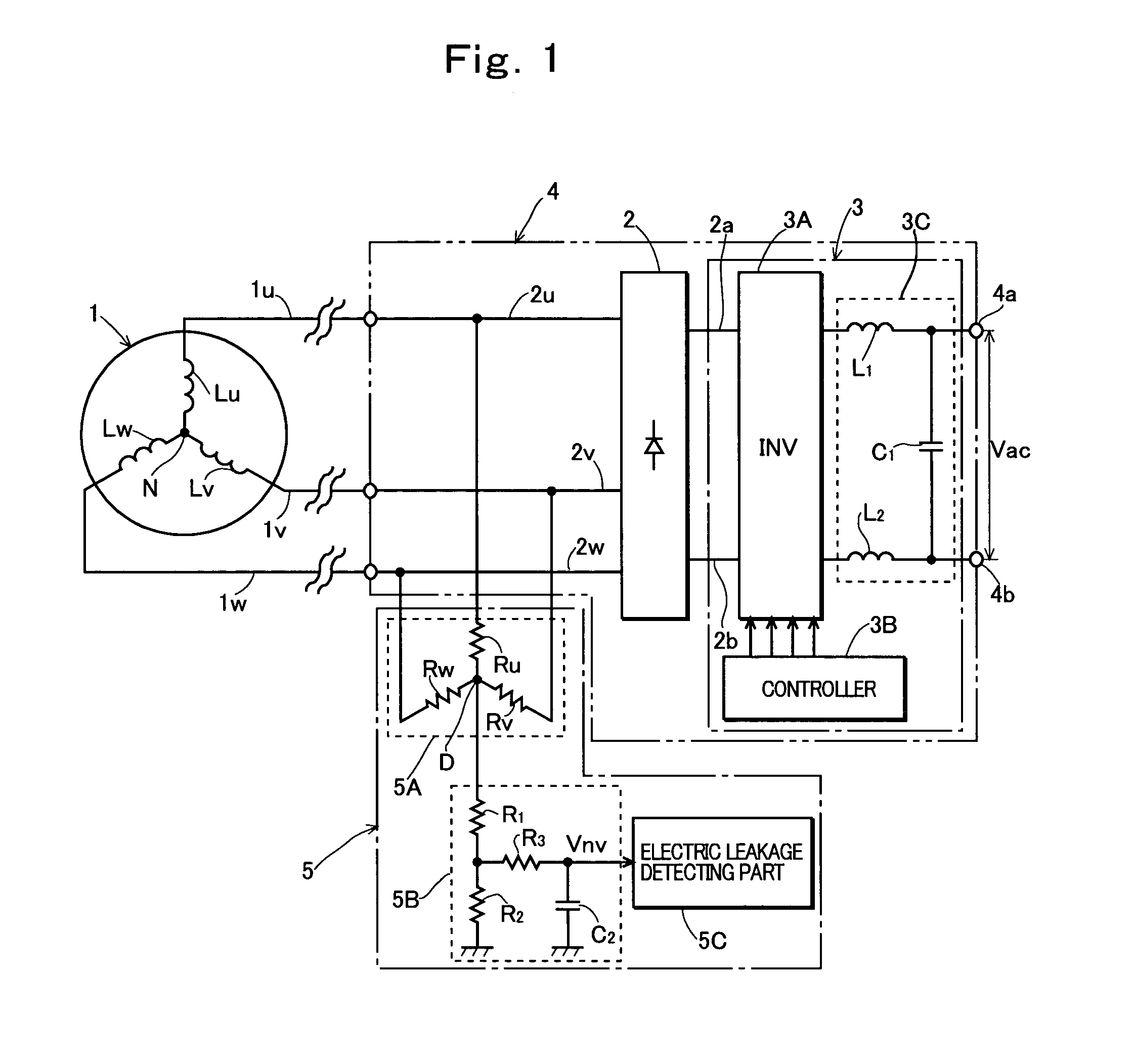
[0034]Preferred embodiments of the present invention will be described in further detail with reference to the accompanying drawings. In an embodiment shown in FIG. 1, there is used, as a power source unit for driving a load, an electric power converter 4 wherein an output of a three-phase AC generator is converted into a DC voltage by a converter, and then the DC voltage is converted into and an AC voltage having a constant frequency by an inverter so as to supply the AC voltage to the load.

[0035]In FIG. 1, a reference numeral 1 denotes a three-phase AC generator driven by a prime mover such as an internal combustion engine, and the AC generator comprises three-phase armature coils Lu to Lw which are star-connected. Three-phase output lines 1u to 1w of the AC generator 1 are connected to three-phase input lines 2u to 2w of a converter 2 which is constituted by a full-wave rectifier circuit, and a voltage across DC output terminals 2a and 2b of the converter 2 is input to an inverte...


PUM


Abstract

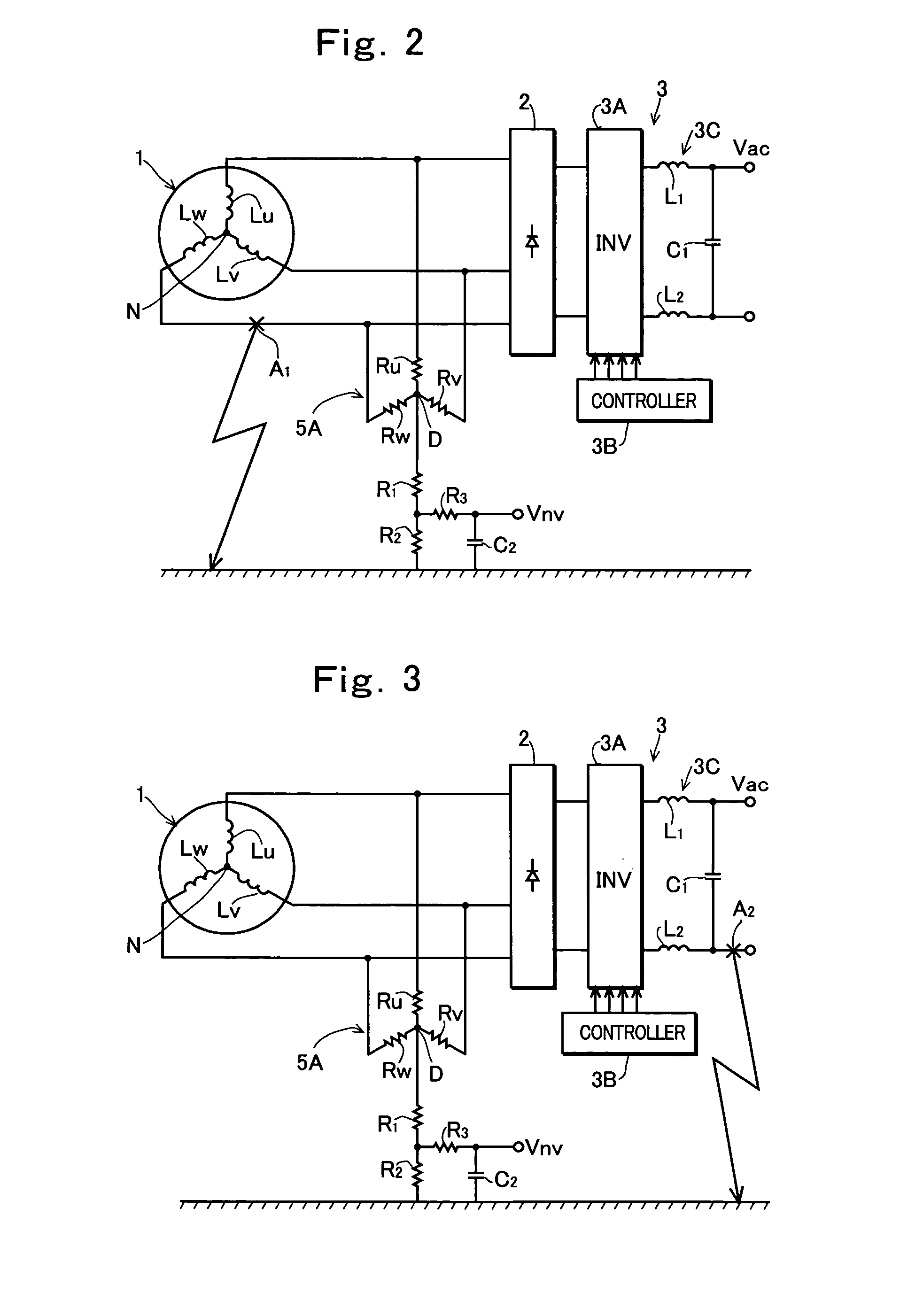
An electric leakage detection system having: a detection point forming circuit which forms a detection point being connected through three resistors which are star-connected to a three-phase output line of an AC generator; a voltage detection circuit which detects a voltage across the detection point and ground; and an electric leakage detecting part which detects existence of an electric leakage from a period of the detected voltage and determines an occurrence position of the electric leakage from a period of the detected voltage.

Description

TECHNICAL FIELD OF THE INVENTION[0001]The present invention relates to an electric leakage detection system which detects an electric leakage of a power source unit for supplying an electric power to a load, using an AC generator as a power source.BACKGROUND OF THE INVENTION[0002]As a device for detecting an electric leakage (ground fault) of a power source unit using an AC generator as a power source, there is proposed an electric leakage detection system wherein an electric leakage is detected by detecting a zero-phase current flowing through a ground line which connects a neutral point of armature coils of a three-phase AC generator to ground, as disclosed in Japanese Patent Application Laid-Open Publication Nos. 10-142282 and 2000-149758.[0003]In such an electric leakage detection system for detecting an electric leakage from a zero-phase current flowing through a ground line which grounds a neutral point of a generator when the electric leakage occurs, it is necessary to lay ar...

Claims


Application Information

Patent Timeline
Patent Type & Authority Patents(United States)
IPC IPC(8): G01R31/08G01R31/02
CPCG01R31/025G01R31/52
Inventor KISHIBATA, KAZUYOSHIENDOU, MASAHIKO
Owner KOKUSAN DENKI CO LTD
Learn More