
Method and system for multipath detection

a multi-path detection and detection method technology, applied in direction finders using radio waves, navigation instruments, etc., can solve the problems of inability to accurately detect the present position of the vehicle by the gps receiver, the difficulty of using an antenna having a directivity of a particular direction for the gps receiver, and the inability to perform multi-path detection efficiently. , the effect of improving the accuracy of position detection

Active Publication Date: 2006-10-03
ALPINE ELECTRONICS INC
View PDF8 Cites 3 Cited by
  • Summary
  • Abstract
  • Description
  • Claims
  • Application Information

AI Technical Summary

Benefits of technology

[0010]In order to solve the above problems, an object of the present invention is to provide a receiver that is capable of detecting multipath of a reception signal with a high accuracy.
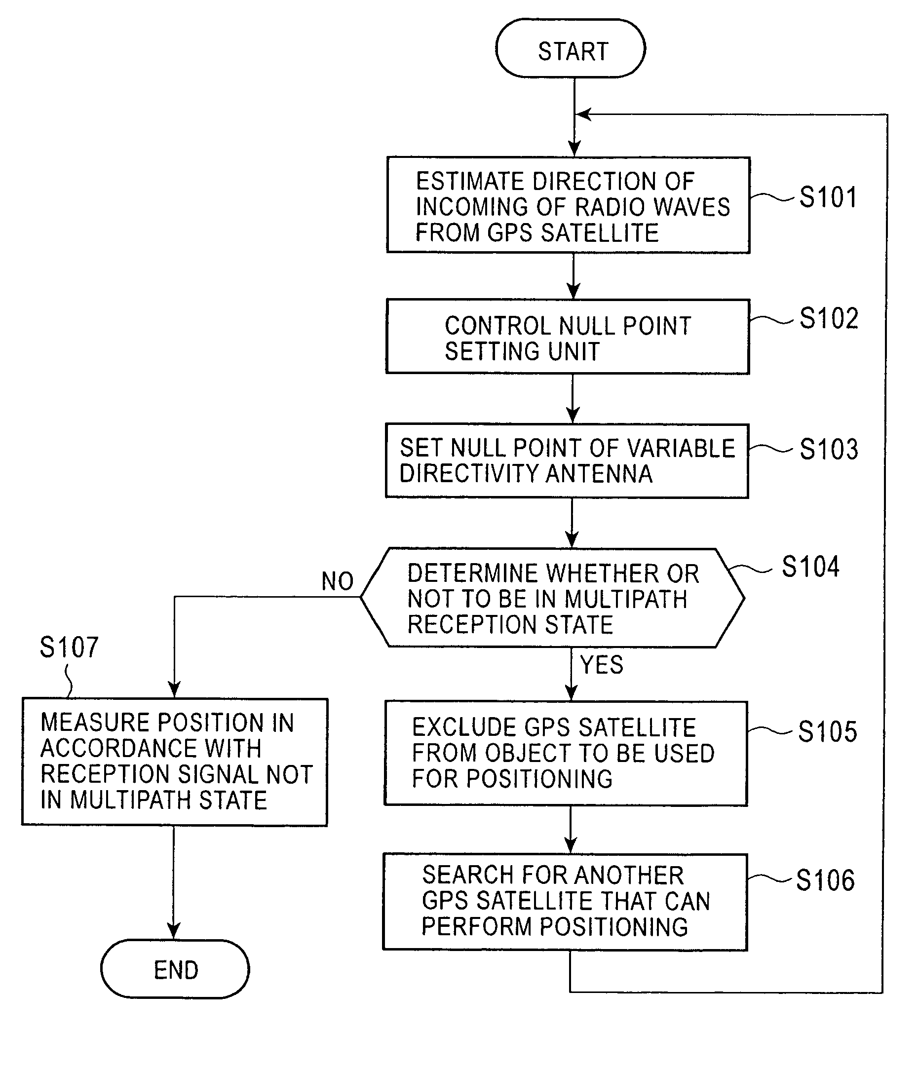
[0017]In an embodiment according to the present invention, a null point of a variable directivity antenna is set to a direction of a satellite that can perform positioning and a reception signal of the antenna is monitored, so that determination of whether the reception signal is in a multipath state can be performed. Thus, multipath detection can be performed efficiently without reducing the intensities of reception signals from satellites that are located in directions other than the direction of the null point. Also, by using the receiver for a navigation system, the position of a movable body is detected using reception signals from satellites that are not in the multipath state. Thus, an accuracy of position detection can be further improved.

Problems solved by technology

However, the known in-vehicle navigation apparatuses described above have problems.
The GPS receiver may not detect the present position of the vehicle accurately under the influence of multipath because an error may occur in position calculation if waves other than pure direct waves from GPS satellites are used for position detection.
It is, however, practically difficult to use an antenna having a directivity of a particular direction for the GPS receiver because the GPS receiver needs to receive radio waves from a plurality of satellites.
This arrangement, however, complicates a circuit configuration of the GPS receiver and increases the cost of the GPS receiver.

Method used


Image

  • Method and system for multipath detection
  • Method and system for multipath detection
  • Method and system for multipath detection

Examples


first embodiment

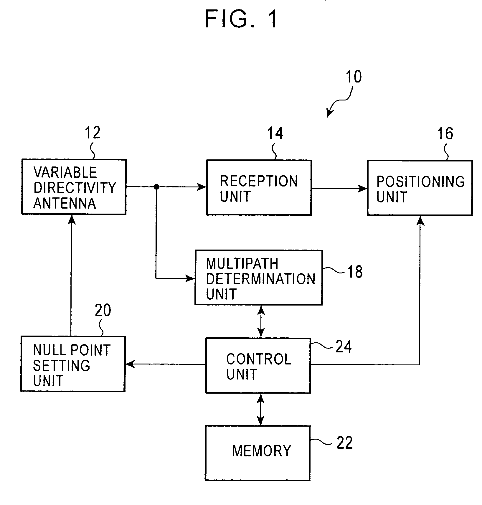
[0030]FIG. 1 is a block diagram showing the structure of a GPS receiver according to the present invention. A GPS receiver 10 includes a variable directivity antenna 12; a reception unit 14 for demodulating reception signals from the variable directivity antenna 12; a positioning unit 16 for measuring positions, such as distances to GPS satellites, using signals from the reception unit 14; a multipath determination unit 18 for receiving the reception signals from the variable directivity antenna 12 and determining whether or not the reception signals are in a multipath state; a null point setting unit 20 for setting a null point at a predetermined angle of a directional pattern of the variable directivity antenna 12; a memory 22 for storing positional information, such as almanac data, of GPS satellites; and a control unit 24 for controlling the operations of these units.

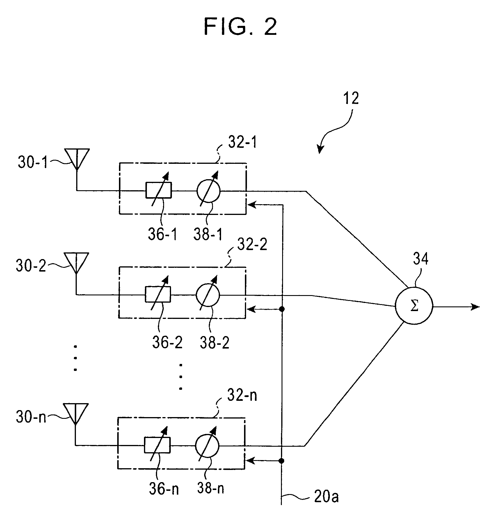
[0031]The variable directivity antenna 12 is equal to a smart antenna or an adaptive antenna. FIG. 2 shows the st...

second embodiment

[0053]The operation for position detection in the navigation system 100 will now be explained. The multipath determination unit 18 of the GPS receiver 10a performs multipath detection for a reception signal, and outputs the detection result to the control unit 24. The control unit 24 causes the input / output unit 50 to output an identification signal of the GPS satellite and a reception condition signal indicating the reception condition in accordance with the detection result. These signals are supplied to the navigation control unit 138 via the receiver control unit 124. The reception condition signal includes information on whether the GPS satellite is in the multipath state, whether a signal of the GPS satellite is being received, whether a signal of the GPS satellite cannot be received, and the like.

[0054]If the reception signal is not in the multipath state, a signal from the positioning unit 16 is sent to the position detection unit 122, so that the position detection unit 12...


PUM


Abstract

A navigation system including a GPS receiver; a variable directivity antenna capable of forming a null point in at least one direction; a null point setting unit for setting the null point of the variable directivity antenna in the direction of a GPS satellite that can perform positioning; and a multipath determination unit for determining whether a reception signal from the variable directivity antenna is in a multipath state in accordance with the reception signal.

Description

BACKGROUND OF THE INVENTION[0001]1. Field of the Invention[0002]The present invention relates to multipath detection methods in global positioning system (GPS) receivers used for detecting the positions of movable bodies, such as vehicles.[0003]2. Description of the Related Art[0004]Receivers, such as GPS receivers, for receiving signals that are spectrum-spread by a direct spread system receive signals from a plurality of earth-orbiting GPS satellites to detect the positions of vehicles, vessels, and the like. GPS receivers using three or more GPS satellites are capable of detecting two-dimensional positions (latitude and longitude). GPS receivers using four or more GPS satellites are capable of detecting three-dimensional positions (longitude, latitude, and altitude).[0005]In-vehicle navigation apparatuses use signals received from the GPS receiver to detect the present position of a vehicle, display a map around the present position of the vehicle on a display, and provide route ...

Claims


Application Information

Patent Timeline
Patent Type & Authority Patents(United States)
IPC IPC(8): G01S1/00H01Q3/22H04B7/185G01C21/00G01S19/22G01S19/25G01S19/36G08G1/0969H01Q3/26
CPCG01S19/22G01S19/36
Inventor OBATA, KIJURO
Owner ALPINE ELECTRONICS INC
Learn More