Method and system for masking dynamic regions in a user interface to enable testing of user interface consistency

a dynamic region and user interface technology, applied in error detection/correction, instruments, computing, etc., can solve problems such as overpowering actual results being examined, and achieve the effect of reducing false positives during tests and reducing the amount of nois

Inactive Publication Date: 2007-11-13
MICROSOFT TECH LICENSING LLC
View PDF11 Cites 90 Cited by
  • Summary
  • Abstract
  • Description
  • Claims
  • Application Information

AI Technical Summary

Benefits of technology

[0005]The present invention provides a system and method for masking dynamic regions of a user interface that assist in testing of the static user interface layout. The masking regions are used to eliminate the regions of the user interface layout that are expected to change during a verification process. The present invention allows a user to add masks to the dynamic areas of a screen for selectively ignoring those areas during testing. Stated differently, the present invention provides a method for reducing the false positives during test that may be caused by dynamic areas of the user interface screen. These false positives can create “noise” in the testing results that may overwhelm the actual results being examined by the testing. The ability to mask out dynamic regions on the screen such as the clock and animations helps reduce the amount of noise created by these dynamic regions. Additionally, the masking functionality allows the testing process to iterate through portions of the user interface (e.g., the menu bar display) without impacting the ability to maintain a baseline snapshot for comparison.

Problems solved by technology

These false positives can create “noise” in the testing results that may overwhelm the actual results being examined by the testing.

Method used


Image

  • Method and system for masking dynamic regions in a user interface to enable testing of user interface consistency
  • Method and system for masking dynamic regions in a user interface to enable testing of user interface consistency
  • Method and system for masking dynamic regions in a user interface to enable testing of user interface consistency

Examples


Embodiment Construction

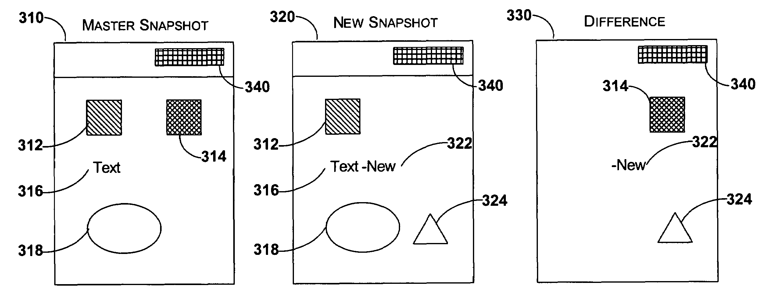
[0012]The present invention now will be described more fully hereinafter with reference to the accompanying drawings, which form a part hereof, and which show, by way of illustration, specific exemplary embodiments for practicing the invention. This invention may, however, be embodied in many different forms and should not be construed as limited to the embodiments set forth herein; rather, these embodiments are provided so that this disclosure will be thorough and complete, and will fully convey the scope of the invention to those skilled in the art. Among other things, the present invention may be embodied as methods or devices. Accordingly, the present invention may take the form of an entirely hardware embodiment, an entirely software embodiment or an embodiment combining software and hardware aspects. The following detailed description is, therefore, not to be taken in a limiting sense.

Illustrative Operating Environment

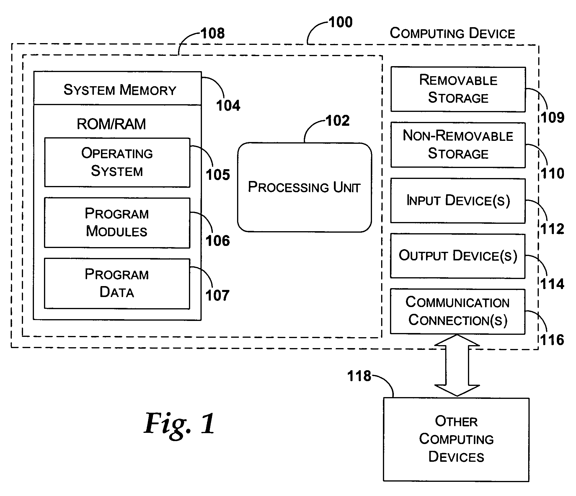
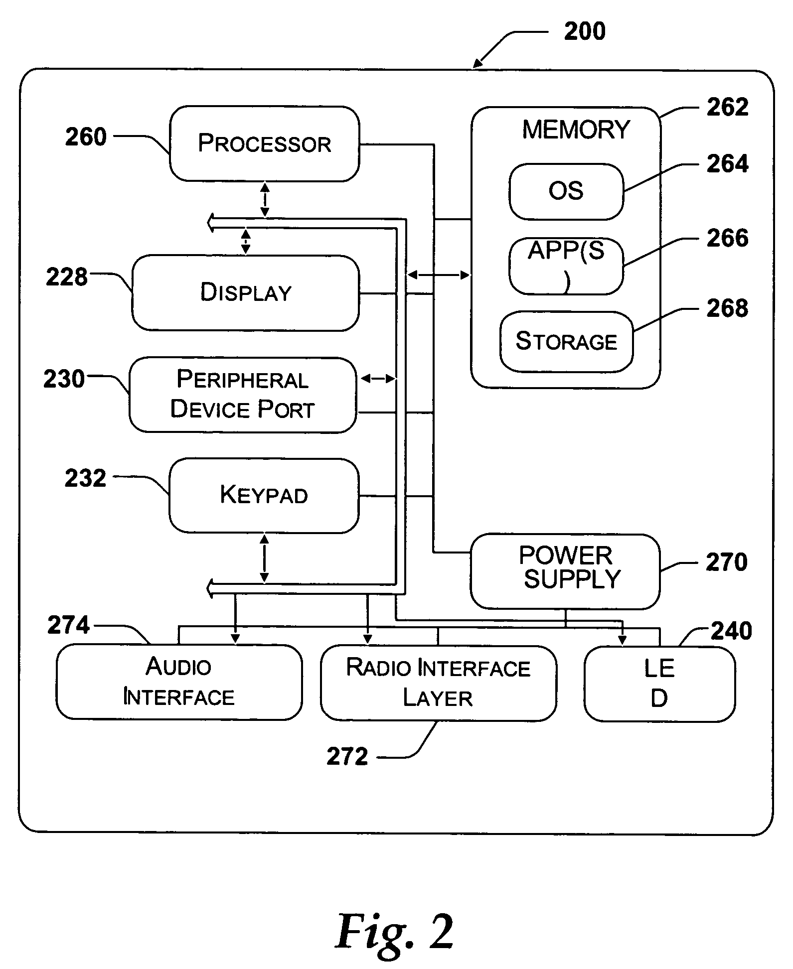
[0013]FIG. 1 shows an exemplary computing device that may b...


PUM


Abstract

A system and method for masking dynamic regions of a user interface that assist in testing of the static user interface layout. The masking regions are used to eliminate the regions of the user interface layout that are expected to change during a verification process. The present invention allows a user to add masks to the dynamic areas of a screen for selectively ignoring those areas during testing.

Description

CROSS-REFERENCE TO RELATED APPLICATION[0001]The present invention is related to a patent application entitled “Method and System for Automatically Determining Differences in a User Interface Throughout a Development Cycle,” filed concurrently with this application. The related application is assigned to the assignee of the present patent application and hereby incorporated by reference.BACKGROUND OF THE INVENTION[0002]Complexity of mobile devices such as cellular phones, personal data assistants (PDAs), handheld computers, and others, continues to increase. The market for such devices is steadily becoming a worldwide market, requiring the devices to provide content in a number of different languages. Each different platform may further include a variety of options that result in different user interface outputs depending on the options selected.[0003]The user interface of the device provides the mechanism through which the content of an application on the device is displayed to a us...

Claims


Application Information

Patent Timeline
Patent Type & Authority Patents(United States)
IPC IPC(8): G06F11/00G06F3/14G06F11/28G06F9/00G06F9/44G06F11/36
CPCG06F11/3688G06F9/00
Inventor DERKS, PATRICK JOSEPHSERES, ANDREWVEERAMACHANENI, JIDESH
Owner MICROSOFT TECH LICENSING LLC
Why Eureka
Try Eureka