Method for manufacturing a perpendicular magnetic recording head

a manufacturing method and technology of a perpendicular magnetic recording head, applied in the field of magnetic recording technology, can solve the problems of difficult repeatability of fabrication of difficult control of the height of conventional poles, and difficulty in manufacturing suitable conventional pmr heads b>10/b>, and achieve the effect of low production yield

Inactive Publication Date: 2007-11-20
WESTERN DIGITAL TECH INC
View PDF58 Cites 169 Cited by
  • Summary
  • Abstract
  • Description
  • Claims
  • Application Information

AI Technical Summary

Problems solved by technology

As a result, the height of the conventional pole 16 may be extremely difficult to control and fabrication of suitable conventional PMR heads 10 difficult to repeat.
Manufacturing of conventional PMR heads 10 may, therefore, have a very low yield.

Method used


Image

  • Method for manufacturing a perpendicular magnetic recording head
  • Method for manufacturing a perpendicular magnetic recording head
  • Method for manufacturing a perpendicular magnetic recording head

Examples


Embodiment Construction

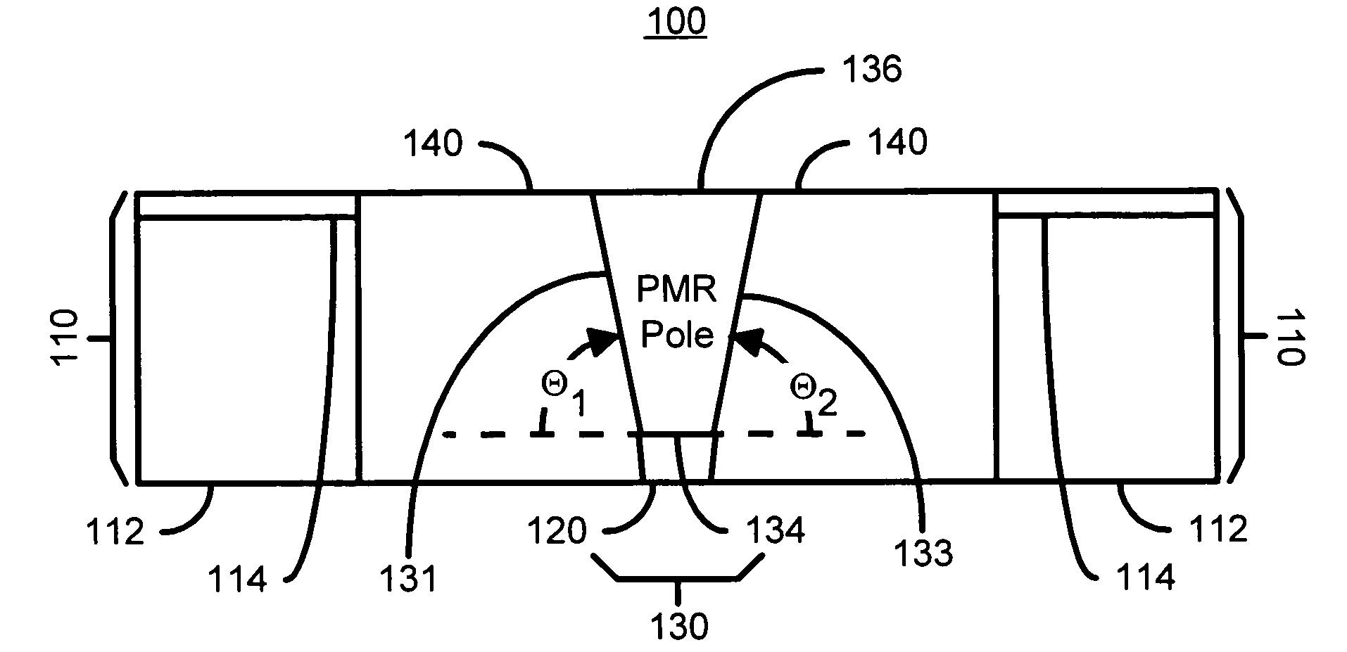
[0014]FIGS. 3A-3E depict one embodiment of a PMR head 100 formed during fabrication in accordance with an exemplary embodiment of the present invention during fabrication. To enhance clarity FIGS. 3A-3E are not drawn to scale. FIG. 3A depicts a preferred embodiment of the CMP uniformity structure 110 used in forming a PMR (not shown in FIG. 3A) pole for the PMR head 100. The CMP uniformity structure 110 includes an aperture 116 therein. The PMR pole for the PMR head 100 is formed in the aperture 116. The CMP uniformity structure 110 used to reduce the variations in the CMP process, as described below. To form the CMP uniformity structure 110, its layer of the CMP uniformity structure 110 are deposited and patterned, generally using photolithography.

[0015]In a preferred embodiment, depicted in FIG. 3A, the CMP uniformity structure 110 includes a CMP support structure 112 and a CMP barrier layer 114. The CMP support structure 112 is insulating and, in a preferred embodiment, includes ...


PUM

PropertyMeasurementUnit
thicknessaaaaaaaaaa
thicknessaaaaaaaaaa
angleaaaaaaaaaa

Abstract

A method and system for manufacturing a perpendicular magnetic recording head is disclosed. The method and system include providing a chemical mechanical planarization (CMP) uniformity structure having an aperture therein and forming a perpendicular magnetic recording pole within the aperture. The CMP uniformity structure may include a CMP barrier layer. The method and system further include fabricating an insulator after formation of the perpendicular magnetic recording pole and performing a CMP to remove a portion of the insulator, expose a portion of the perpendicular magnetic recording pole and planarize an exposed surface of the perpendicular magnetic recording head.

Description

FIELD OF THE INVENTION[0001]The present invention relates to magnetic recording technology, and more particularly to a method and system for fabricating a perpendicular recording head.BACKGROUND OF THE INVENTION[0002]FIG. 1 depicts a portion of conventional perpendicular magnetic recording (PMR) head 10 as viewed from the air-bearing surface (ABS). The conventional PMR head 10 includes a conventional pole 16 and a top shield 24 separated by a write gap 20. Note that the top shield 24 also acts as pole during writing using the conventional PMR head 10. The conventional pole 16 and the top shield 24 are surrounded by insulating layers 18 and 22. The conventional pole 16 resides on a seed layer 12 and has sidewalls 14.[0003]In conventional applications, the height of the conventional pole 16 is typically less than approximately three-tenths micrometer. The conventional pole 16 also has a negative angle such that the top of the conventional pole 16 is wider than the bottom of the conven...

Claims


Application Information

Patent Timeline
Patent Type & Authority Patents(United States)
IPC IPC(8): G11B5/127H04R31/00
CPCG11B5/1278G11B5/3116G11B5/3163G11B5/3169Y10T29/49046Y10T29/49039Y10T29/49048Y10T29/49043Y10T29/49052
Inventor YANG, DANNINGCHEN, YINGJIANNEASE, BRANTSIN, KYUSIK
Owner WESTERN DIGITAL TECH INC
Why Eureka
Try Eureka