Water curtain apparatus and method

a technology of water curtain and water curtain rod, which is applied in the direction of lighting and heating apparatus, heating types, separation processes, etc., can solve the problems of large amount of electricity, rippling effect of falling water, and limitations inherent in ambient humidity reducing efficacy, and achieve the effect of low viscosity

Active Publication Date: 2007-11-20
HAYDEN JOHN B
View PDF43 Cites 23 Cited by
  • Summary
  • Abstract
  • Description
  • Claims
  • Application Information

AI Technical Summary

Problems solved by technology

This panel may also have indentures that cause a rippling effect in the falling water.
Heat exchange air conditioning, the most popular, consumes large amounts of electricity, and uses chemicals to transport heat that are considered potentially harmful to the environment.
Limitations are inherent to ambient humidity reducing efficacy, and the large volumes of air that must be moved.
The use of evaporative cooling and air conditioning when run simultaneously in an area cancel out their cooling benefits, since one introduces humidity and the other removes humidity.
These however release large volumes of water into the air and can saturate objects nearby.
They are additionally prone to clogging due to mineralization and since they rely on high pressure to mist flooding can occur if compromised.
Furthermore, indoor air purification systems require constant cleaning and electricity to function.
These systems only clean air once it is inside by recirculation.
The waterfalls described previously, and others like them, all suffer from a number of distinct disadvantages, such as considerable water droplet splashing over a range of several feet from the base of the waterfalls; significant evaporation of water to the point that refill may be required daily; risk of water spillage during relocation of the waterfall; and a large base to house a lower reservoir and a means for returning water to the upper reservoir.
One of the problems with such devices is that they are primarily designed for use with large volumes of water, which makes it difficult to use the devices in indoor water displays.
Moreover, such prior art waterfall displays do not form a continuous film or layer of downwardly flowing water, but rather form thick, turbulent streams which tend to splash and are not particularly attractive as a decorative display.
However, the known indoor water displays do not create an unsupported film or laminar sheet of water.
One of the problems associated with the existing advertising display devices is that in order to function, they require the use of viscous fluids, such as lubricating oil.
Lefevre, Jr. however, is limited to maintaining a thin film of viscous liquid.
Another problem associated with the Lefevre, Jr. device is that in order to maintain contact between the viscous liquid and two guides, it relies on forming the guides such that they converge at the bottom of the device.
As a result of these deficiencies, the device disclosed would not be able to maintain a film of aqueous liquid.
The Lipski device is similarly not suited for low viscosity liquids, such as water or aqueous liquids which have low molecular adhesion and high molecular cohesion.
However the apparatus and materials conventionally implemented present major drawbacks due to complexity of operation, restrictive dimensions, low mechanical ruggedness, bad endurance over time and vulnerability to bad weather.
Accordingly, until now the proposed systems fail to meet a certain number of requirements.
The devices disclosed in the aforementioned patents suffer from many deficiencies as described above.

Method used


Image

  • Water curtain apparatus and method
  • Water curtain apparatus and method
  • Water curtain apparatus and method

Examples


Embodiment Construction

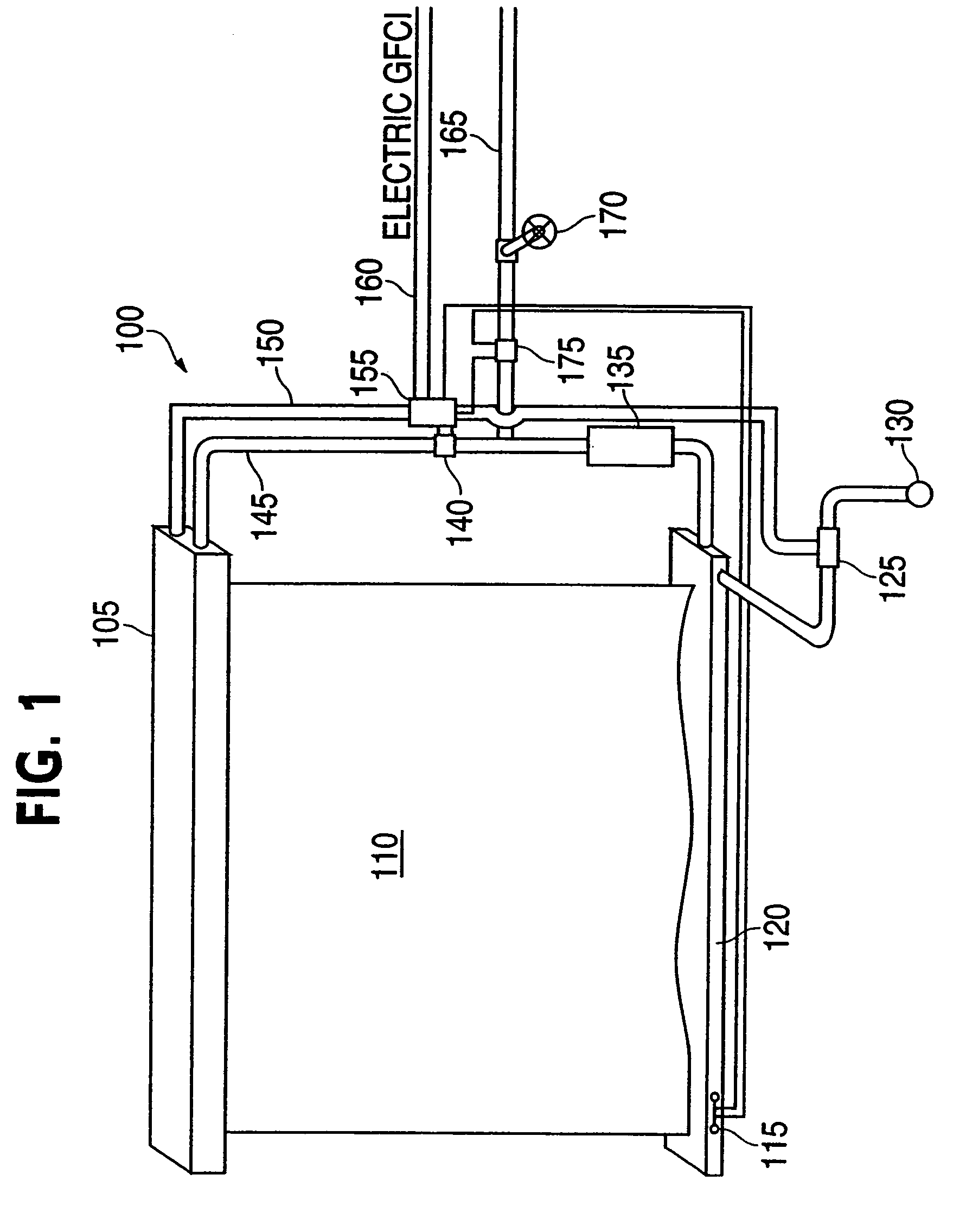
[0040]The invention will now be described with reference to the drawing figures, in which like reference numerals refer to like parts throughout. As shown in FIG. 1, an embodiment in accordance with the present invention provides a water curtain or drape assembly 100 having a drape hood 105, material drape 110, float overflow shut-off 115, collection return 120, a drainage line solenoid 125 which preferably is electric, a drainage line 130, a filter 135, drape solenoid 140 which preferably is electric, a drape feed line 145, a pump 240, a pump power line 150, an on / off switch 155 to a power source 160 which preferably is a ground fault circuit interrupter (GFCI) power line for obvious safety concerns, a feed line 165, and a shutoff valve 170.

[0041]The present invention, wherein in one aspect provides that in some embodiments may include a decorative, useful and educational indoor waterfall which utilizes a low viscosity liquid, such as water or other aqueous liquid, to form an attra...


PUM

PropertyMeasurementUnit
ninety degree angleaaaaaaaaaa
translucentaaaaaaaaaa
velocityaaaaaaaaaa

Abstract

An evaporative cooler comprises a housing having an upper surface and at least one vertical wall defining a chamber. The upper surface can include at least one opening in communication with the chamber. The evaporative cooler can also comprise at least one drain slit assembly for distributing a fluid and further comprise at least one screen. The screen can define a portion of the vertical wall. The screen can have an interior surface and an exterior surface relative to the chamber. In addition, the screen can be disposed relative to the drain slit assembly such that the drain slit assembly distributes the fluid over the screen. The screen can be configured such that the fluid forms a surface fluid layer over the surfaces of the screen. The evaporative cooler can further comprise an air conveyor disposed within the housing for drawing air through the opening and into the chamber such that the air is conveyed through the screen and the fluid layer.

Description

CROSS-REFERENCE TO RELATED APPLICATIONS[0001]This application claims priority to and is a continuation-in-part of U.S. patent application entitled, “Water Curtain Apparatus and Method,” filed Mar. 17, 2005, having a Ser. No. 11 / 081,735, now pending, the disclosure of which is hereby incorporated by reference in its entirety.FIELD OF THE INVENTION[0002]The present invention relates generally to a water curtain apparatus. More particularly, the present invention relates to a film or sheet-type water curtain apparatus and method.BACKGROUND OF THE INVENTION[0003]Water from a reservoir running over a dam, in such a manner as to create a dispersion, is noted to produce aesthetically and acoustically pleasing effects, including a cooling effect as well as a change in humidity in areas nearby. It is noted that this same effect can be duplicated in an artificial waterfall by using a thin angled panel, and allowing water to run down the panel. This panel may also have indentures that cause a ...

Claims


Application Information

Patent Timeline
Patent Type & Authority Patents(United States)
IPC IPC(8): B01F3/04
CPCB05B17/085F24F6/02Y10S261/43F24F2006/003F24F2006/001
Inventor HAYDEN, JOHN B.
Owner HAYDEN JOHN B
Why Eureka
Try Eureka