Cooling assembly

a cooling assembly and cooling device technology, applied in air humidification systems, heating types, lighting and heating apparatus, etc., can solve the problems of limited water supply, limited use, and insufficient quantities of water, and achieve the effects of convenient transportation, simple, reliable, and convenient operation

Inactive Publication Date: 2005-04-14
GPM INC
View PDF8 Cites 24 Cited by
  • Summary
  • Abstract
  • Description
  • Claims
  • Application Information

AI Technical Summary

Benefits of technology

[0013] In one embodiment, the air conditioning assembly according to the present invention comprises a shell and tube heat exchanger wherein ambient air is forced through both sides and discharged approximately together into the interior of the structure that is to be cooled. For convenience, the air streams from the two sides can be combined into one combined stream before being discharged into the interior of the structure, or they may be discharged separately into the structure. This heat exchanger is particularly suited for use in the high heat and low humidity conditions that are typically found during the summer months in deserts. The air conditioning assembly is particularly effective in situations where the temperature is above approximately 80 degrees Fahrenheit, and the relative humidity is below approximately 40 percent, and, preferably, below approximately 35 percent. The assembly is suitably operable even in situations where the structure to be air conditioned is not tightly sealed, that is where there may be openings through the structure that are substantially unobstructed to air flow having as much as, for example, six square inches to a square foot or two of area. Barns, tents, temporary structures and the like are provided with an efficient, reliable, economical, simple, and effective air conditioning system according to the present invention. The air conditioning system according to the present invention does not require an elaborate or expensive installation for its functioning. It can be easily transported to and set up inside of a temporary structure such as, for example, a tent.
[0016] Water in the cold water sump is refrigerated by the refrigeration compressor located in the top section of the design. Cold water from the cold water sump is introduced into the evaporative cooling chamber through a distribution header. The cold water saturates an evaporative media which surrounds or otherwise contacts the riser tubes in the cooling chamber. Air is introduced into the cooling chamber by means of oppositely arranged fans mounted on sidewalls of the cooling chamber which create a turbulent air flow in the cooling chamber and which enhance the evaporative cooling process. Cooled air from the cooling chamber can be discharged through a suitable duct to the interior of the structure to be cooled.

Problems solved by technology

A source of electrical power is required to operate such systems, so the cost of operation is a limitation on their use.
Conventional evaporative coolers consume considerable quantities of water so their use is limited to areas where water is available.
Sufficient quantities of water are not always available in desert environments.
Other types of air conditioning systems require sealed buildings, expensive and high maintenance equipment, and are expensive to operate.
Typically, such structures are not provided with air conditioning systems because of the cost of operating them and the general ineffectiveness of air conditioning systems in such structures.
Most air conditioning systems operate on electricity, and electricity is not always available, or is not available at a reasonable price where the structures are located.
One problem with this system is that it causes excess humidity within the building resulting in algae and bacteria problems.
The disclosed rate of water consumption is very high.

Method used


Image

  • Cooling assembly
  • Cooling assembly
  • Cooling assembly

Examples


Embodiment Construction

[0043] The detailed description of the invention will now be provided with respect to two different preferred embodiments:

[0044] Low Humidity Air Conditioner Embodiment:

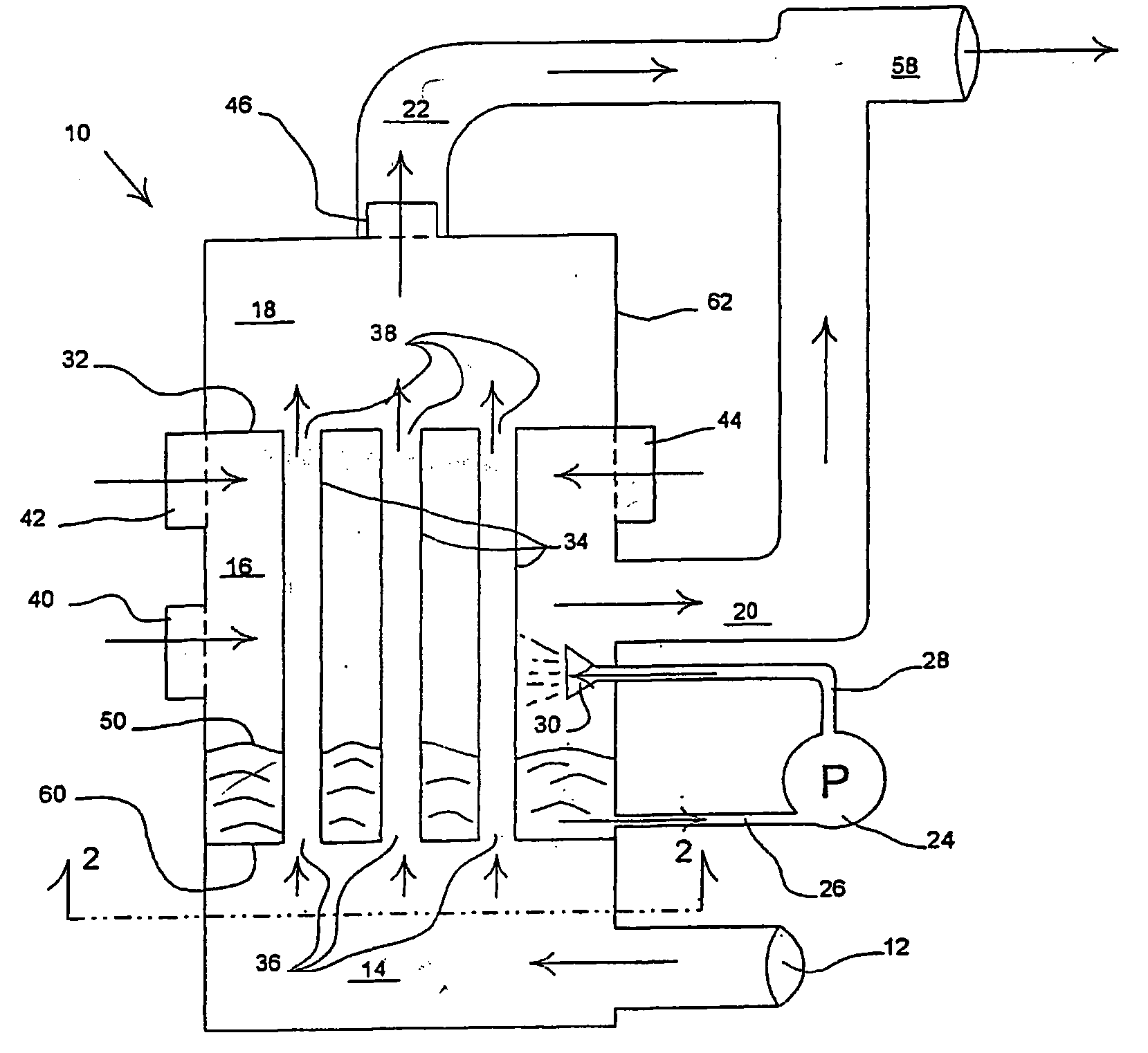
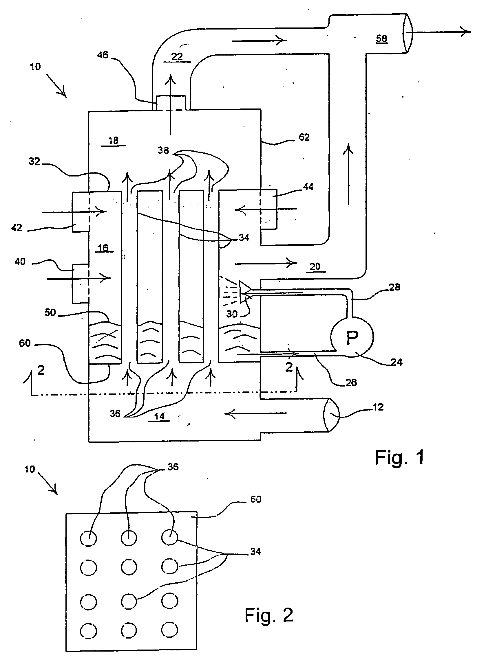
[0045] Referring now to the drawings wherein like reference numerals designate identical or corresponding parts throughout the several views, there is illustrated generally at 10 a tube and shell heat exchanger, which is particularly adapted for use as a low power air conditioning unit in high temperature, low humidity conditions with structures that are not hermetically sealed. The floor plan of such a structure is indicated generally at 64 in FIG. 5.

[0046] Heat exchanger 10 is confined within external case 62. For purposes of illustration, external case 62 is shown as rectangular, but other arcuate, spherical, or cylindrical forms are contemplated within the scope of the present invention.

[0047] Air, preferably internal air from near the ceiling of a structure that is to be cooled, is drawn into the tube side o...


PUM


Abstract

A process and the required apparatus for air conditioning the interior of a structure is shown which can be run entirely off a DC power source, such as a storage battery. A shell and tube heat exchanger is combined with a mechanical refrigeration system to provide a wet shell side and a dry tube side of the apparatus. In the operation of the air conditioner, a mass of distributed water is established on the wet shell side, and a flow of ambient air is passed through the wet shell side to form a resulting stream of moist air. A flow of ambient air is passed through the dry tube side and a resulting stream of dry cooled air is recovered. The streams of most and cooled air can either be combined or routed separately depending primarily upon the humidity of the surrounding environment to be cooled. The air conditioning unit is not hermetically sealed and the water consumption rate is generally less than that required for a conventional evaporative cooler.

Description

CROSS REFERENCE TO RELATED APPLICATIONS [0001] This application is a continuation-in-part of my earlier filed application Ser. No. 10 / 629,121, filed Jul. 28, 2003, and which claimed the benefit of U.S. Provisional Application No. 60 / 405,584, filed Aug. 23, 2002.BACKGROUND OF THE INVENTION [0002] 1. Field of the Invention [0003] The present invention relates in general to low power air conditioning systems, and, in particular, to a low power air conditioning system employing a tube and shell heat exchanger for use in arid conditions and to a combination direct / indirect evaporative cooler with refrigerated sump water for use in other environments. [0004] 2. Description of the Prior Art [0005] In one embodiment, the present invention provides air conditioning for structures that are located in arid, high temperature environments, such as deserts. Such environmental control is essential to enjoying a good quality of life, and, in some instances, is essential to supporting life. This is ...

Claims


Application Information

Patent Timeline
Patent Type & Authority Applications(United States)
IPC IPC(8): F24F1/0071F24F5/00F24F6/04F28D5/00F28D7/16
CPCF24F5/0035F24F6/043Y02B30/545F28D5/00F28D7/1653F24F2001/0085F24F1/0007Y02B30/54F24F1/0071
Inventor PRUITT, ROGER
Owner GPM INC
Why Eureka
Try Eureka