Square porous ceramic vertical tube type dew point indirect evaporative cooler

An evaporative cooler and porous ceramic technology, applied in the field of air conditioning and refrigeration, can solve the problems of low humidity, increased energy consumption of heat exchangers, and heavy maintenance workload, achieving high heat and moisture exchange efficiency, obvious energy-saving advantages, and extended The effect of exposure time

Inactive Publication Date: 2008-12-24
XI'AN POLYTECHNIC UNIVERSITY
View PDF0 Cites 24 Cited by
  • Summary
  • Abstract
  • Description
  • Claims
  • Application Information

AI Technical Summary

Problems solved by technology

However, the existing dew-point indirect evaporative coolers have obvious deficiencies in materials and structures. The materials have poor hydrophilicity, corrosion resistance, and low humidity. Most of them are plate-type in structure. High efficiency, but due to the narrow primary and secondary air channels of the heat exchanger (2-3mm), the dust in the air and the scale formed by the secondary air channels are prone to fouling and blockage, and the secondary air channels are prone to form water bridges It will lead to water blockage, increase the energy consumption of the heat exchanger, and the heat exchange efficiency will drop sharply, and the maintenance workload will be heavy and the service life will be short

Method used


Image

  • Square porous ceramic vertical tube type dew point indirect evaporative cooler
  • Square porous ceramic vertical tube type dew point indirect evaporative cooler
  • Square porous ceramic vertical tube type dew point indirect evaporative cooler

Examples


Embodiment Construction

[0022] The present invention will be described in detail below in conjunction with the accompanying drawings and specific embodiments.

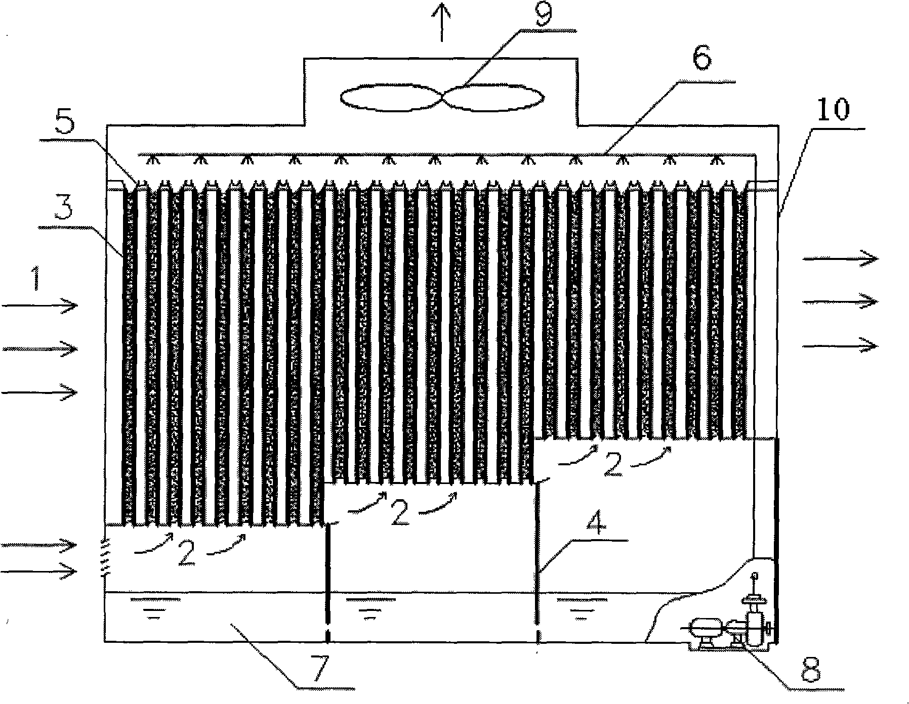
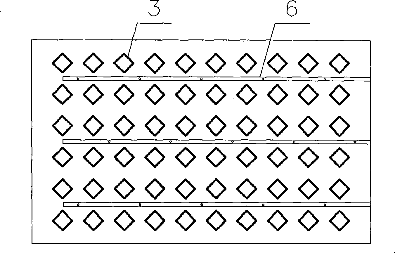
[0023] figure 1 What is shown is an embodiment of a square porous ceramic standpipe dew point indirect evaporative cooler provided by the present invention. In the cooler housing 10, the cooler core, the water distribution device on the upper part of the cooler core, the blower fan 9, and the water reservoir 7 and the water pump 8 on the lower part of the cooler core are set.

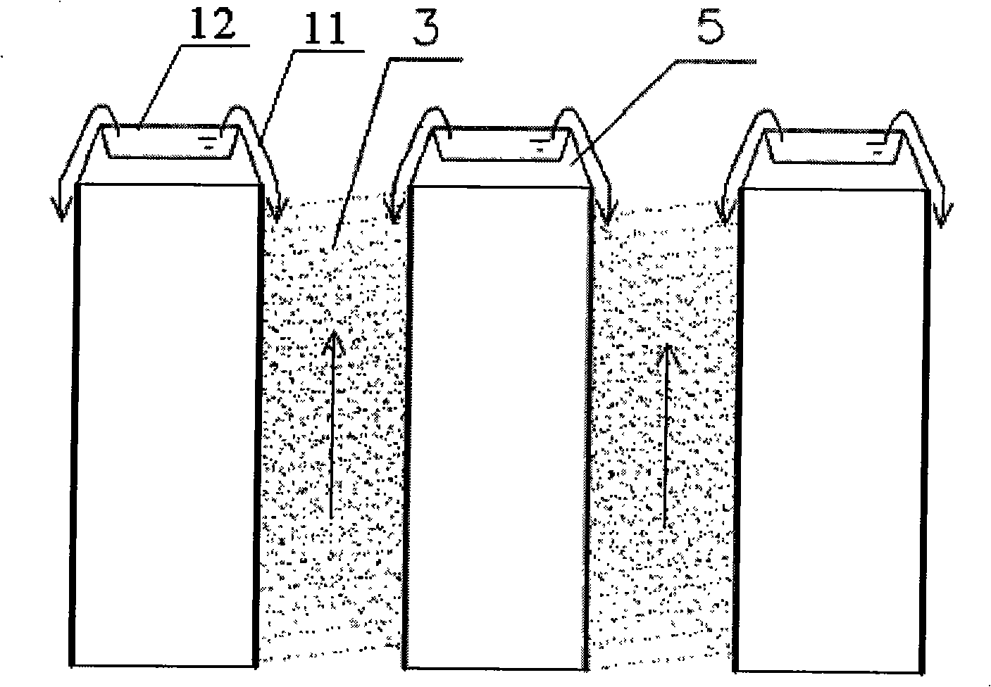
[0024] The core of the cooler, the heat exchange tubes 3 are arranged vertically and in parallel to form a matrix form of multiple rows and columns. The heat exchange tubes 3 are made of porous ceramic materials, and the outside of the tubes is covered with a film made of the same material. The combination of the two up to avoid moisture penetration. The cross section of the heat exchange tube 3 is square, so that the diagonal direction of the square tube cross secti...


PUM


Abstract

The invention discloses a square porous ceramics vertical-tube dew point indirect evaporation cooler device comprising a cooler core, a water-distributing device, a fan, a water-storage and a pump which are arranged inside a cooler casing. The cooler core is formed by a plurality of heat exchanging tubes which are vertically arranged to form a multi-line multi-row matrix form which is divided into three sections; the length of the three sections of heat exchanging tube decreases progressively along a first-time air feeding direction, and clapboards are arranged between each two sections of heat exchanging tube; the water-distributing device comprises a diversion grid and a spraying tube which are arranged on the top of each heat exchanging tube. The structure of the invention leads the first-time air to horizontally pass the square ceramics bundle and leads a second-time air to flow through the bundle from bottom to top; then the first-time air sequentially passes through the three sections of the core and the temperature of the air entering the second-air channels from different section is decreased gradually, and the temperature of the final wet-bulb is also decreased gradually after a heat and moisture exchanging with water. The structure of the invention can greatly enhance the heat and moisture exchanging efficiency and the water distribution becomes more equal so as to lead the temperature of vented air to approach that of the dew point.

Description

technical field [0001] The invention belongs to the technical field of air-conditioning and refrigeration, and relates to an evaporative cooler for air-conditioning, in particular to a square porous ceramic standpipe dew-point indirect evaporative cooler capable of reducing the air temperature to a temperature close to the dew point. Background technique [0002] Traditional indirect evaporative coolers use the temperature difference between dry and wet bulbs of the air to cause or expand the heat transfer temperature difference. This kind of indirect evaporative cooler that makes the air temperature close to the wet bulb temperature has a smaller temperature drop. If only one stage is used This kind of common indirect evaporative cooler can't achieve substantial cooling, and its application range is greatly limited. [0003] In order to achieve greater air temperature drop, dew point indirect evaporative cooling technology came into being. It provides air with a dry bulb t...

Claims


Application Information

Patent Timeline
Patent Type & Authority Applications(China)
IPC IPC(8): F24F13/30
Inventor 黄翔毛秀明文力狄育慧
Owner XI'AN POLYTECHNIC UNIVERSITY
Why Eureka
Try Eureka