Hand-held instrument holder for surgical use

a technology for surgical instruments and holders, applied in the field of surgical instrument holders, can solve the problems of difficult thorough cleaning of these devices, ineffective cleaning of instruments, and inability to clean instruments properly,

Inactive Publication Date: 2007-11-20
VIANT AS&O HLDG LLC
View PDF36 Cites 86 Cited by
  • Summary
  • Abstract
  • Description
  • Claims
  • Application Information

AI Technical Summary

Benefits of technology

[0007]In a feature of the invention, the holder is adapted to hold a large AO fitting.
[0008]In another feature of the invention, the holder is adapted to hold a small AO fitting.

Problems solved by technology

A surgical instrument, for example for preparing for the fitting of a hip prosthesis, works in a medium which causes considerable soiling of the instrument and of the instrument holder.
Despite the importance of doing so, the thorough cleaning of these devices is difficult.
Surgical instrument holders of the prior art are designed such that washing and rinsing are generally not an effective way of cleaning the instrument.
This is due to the small spaces left between component parts which allow only minimal access by cleaning agents.

Method used


Image

  • Hand-held instrument holder for surgical use
  • Hand-held instrument holder for surgical use
  • Hand-held instrument holder for surgical use

Examples


first embodiment

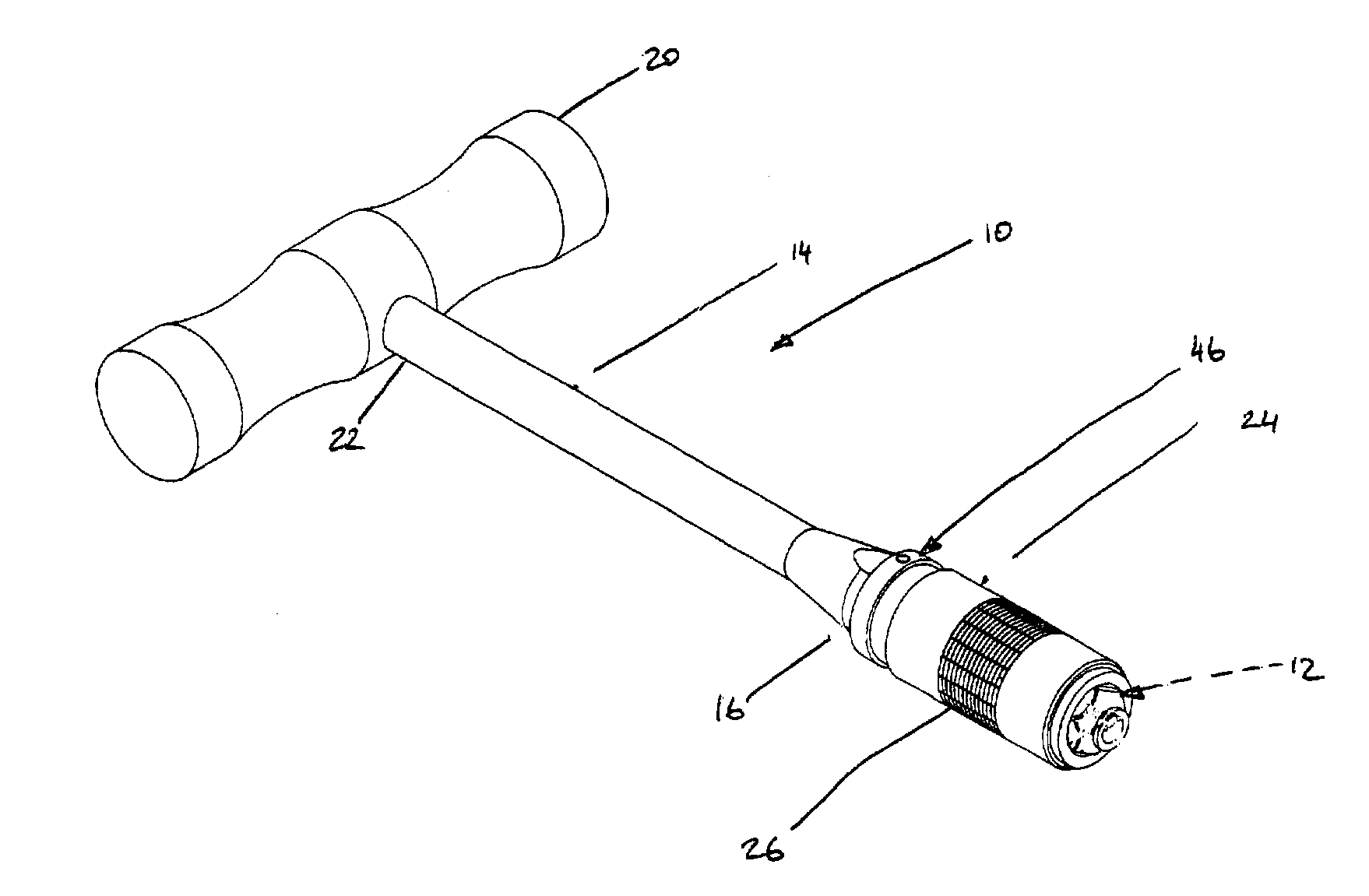
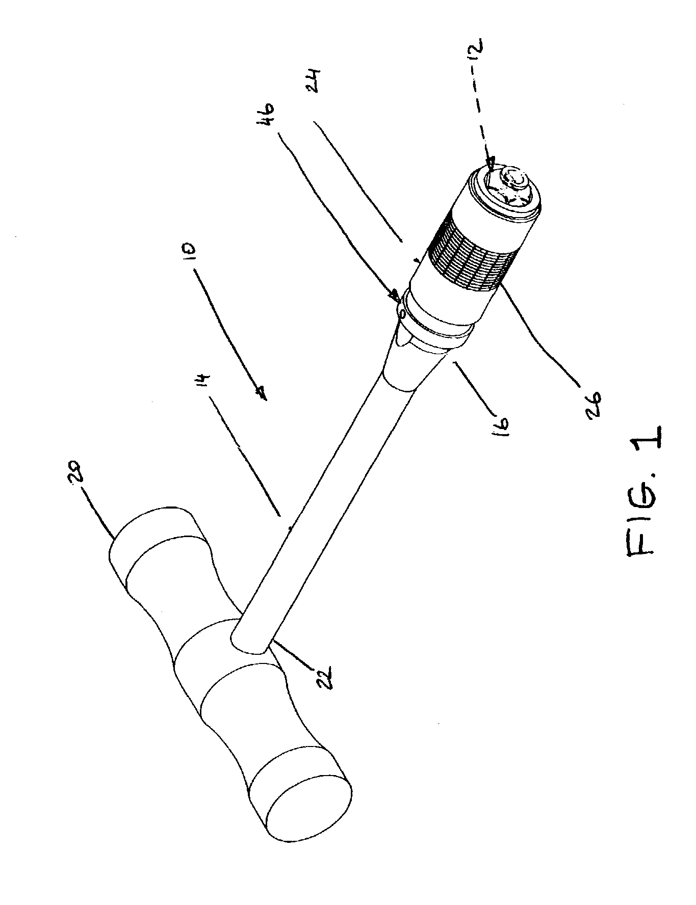
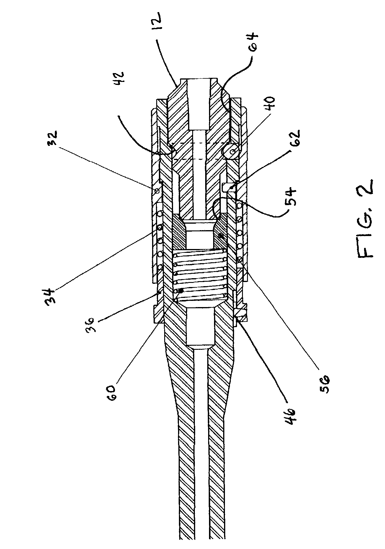
[0017]Referring now to FIGS. 1 and 2, in which the surgical instrument holder 10 of the invention is shown, the holder connects to a surgical instrument 12 to enable controlled manipulation of that instrument. The holder 10 has a shank 14 having a coupling end 16, a T-bar handle 20 attached to an opposite end 22 of the shank, a coupling device 24, and a locking mechanism 26. The coupling end 16 has an internal recess 30 therein, co-axial with the central axis of the shank, for receiving the instrument 12. The locking mechanism 26 is made up of an annular locking sleeve 32, a helical compression spring 34, a ring 36 which slides on the shank 14, and ball-detents 40. Preferably, to ensure that the instrument 12 is retained in an axially aligned relationship with the holder 10, three, circumferentially spaced apart ball-detents 40 arc disposed in the coupling end 16 of the shank 14. It should be noted that the balls 44 are held in their respective detents via any known means of doing s...

second embodiment

[0025]Referring now to FIG. 4, in which is shown the instrument holder 10′ of the invention, the holder has a shank 14′ having a coupling end 16′, a T-bar handle 20′ attached to an opposite end 22′ of the shank, a coupling device 24′, and a locking mechanism 26. The coupling end 16′ has an internal recess 30′ therein, co-axial with the central axis of the shank, for receiving an instrument 12′, which is a small AO fitting (shown most clearly in FIG. 7). The locking mechanism 26′ is made up of an annular locking sleeve 32′, a helical spring 34′, a ring 36′ which slides on the shank 14′, and a ball-detent 40′. The annular locking sleeve 32′ mounts so as to slide along the shank 14′. The ball-detent 40′ is disposed in the coupling end 16′ of the shank 14′ and received into an annular recess 42′ in the instrument 12′. The locking sleeve 32′ slides over the ball-detent 40′ to bias the ball 44′ into the recess 42′ in order to lock the instrument 12′ in place as well as to minimize play in...


PUM

PropertyMeasurementUnit
circumferenceaaaaaaaaaa
lengthaaaaaaaaaa
diameteraaaaaaaaaa

Abstract

A surgical instrument holder has a shank having a coupling end, a handle attached to an opposite end of the shank, a coupling device, and a locking mechanism. The coupling end has an interface thereon for receiving an instrument. The locking mechanism has an annular locking component, a spring, a ring which slides on the shank, and a locking device. The annular locking component is mounted so as to slide along the shank. The locking device cooperates with the locking component so as to lock the instrument onto the interface. The spring biases the locking component in a locking direction and bears on the ring. The ring is disengageably lockable to the shank via a connection device so as to enable quick disassembly for cleaning and component sterilization.

Description

CROSS REFERENCE TO RELATED APPLICATIONS[0001]This application is a continuation-in-part of U.S. patent application Ser. No. 10 / 391,464, entitled instrument Holder for a Surgical instrument, filed on Mar. 18, 2003 and now U.S. Pat. No. 7,056,317, which is in turn continuation of Ser. No. 09 / 902,369 filed on Jul. 9, 2001, U.S. Pat. No. 6,540,739 which in turn is a continuation of Ser. No. 09 / 602,341 filed Jun. 24, 2000 and now U.S. Pat. No. 6,264,647 issued Jul. 24, 2001, the contents of which are incorporated herein by reference thereto.BACKGROUND OF THE INVENTION[0002]This invention relates to surgical instrument holders, and more particularly, to hand-held holders of rotary surgical cutting tools.[0003]Surgical instruments and their respective holders have to be kept clean and sterile before any use in a hospital environment in order to minimize risk of transfer of disease or infection from patient to patient following the emergence of certain “prions” that are not killed by normal...

Claims


Application Information

Patent Timeline
Patent Type & Authority Patents(United States)
IPC IPC(8): B23B31/107A61B17/00A61B17/16A61B19/00
CPCA61B17/1666A61B17/1617A61B2017/00464A61B2019/4868Y10T279/3481Y10T408/907Y10T279/17717Y10T279/17803Y10T279/32Y10T279/17752Y10T408/953A61B2090/0813A61B17/16A61B17/00
Inventor LECHOT, ANDREFEHLBAUM, PHILIPPE
Owner VIANT AS&O HLDG LLC
Why Eureka
Try Eureka