Push-pull plugs and tools

a technology of push-pull plugs and tools, which is applied in the direction of coupling device connection, coupling device engaging/disengaging, electrical equipment, etc., can solve the problems of occupying a certain amount of floor space, becoming more difficult to plug in and unplug connectors, and difficult for a technician to reach

Inactive Publication Date: 2007-11-20
PANDUIT
View PDF39 Cites 87 Cited by
  • Summary
  • Abstract
  • Description
  • Claims
  • Application Information

AI Technical Summary

Problems solved by technology

For example, many enterprises employ racks for their networking equipment, and the racks take up a certain amount of floor space.
But as connection density is increased, it becomes more difficult to plug in and unplug connectors.
Because the plugs are very close to one another, it is difficult for a technician to reach between adjacent plugs in order to operate a latch on a plug and thereby release the plug.
It is also difficult to hold a plug during insertion.
The high density of cables coming out of the plugs adds to these difficulties.

Method used


Image

  • Push-pull plugs and tools
  • Push-pull plugs and tools
  • Push-pull plugs and tools

Examples


Embodiment Construction

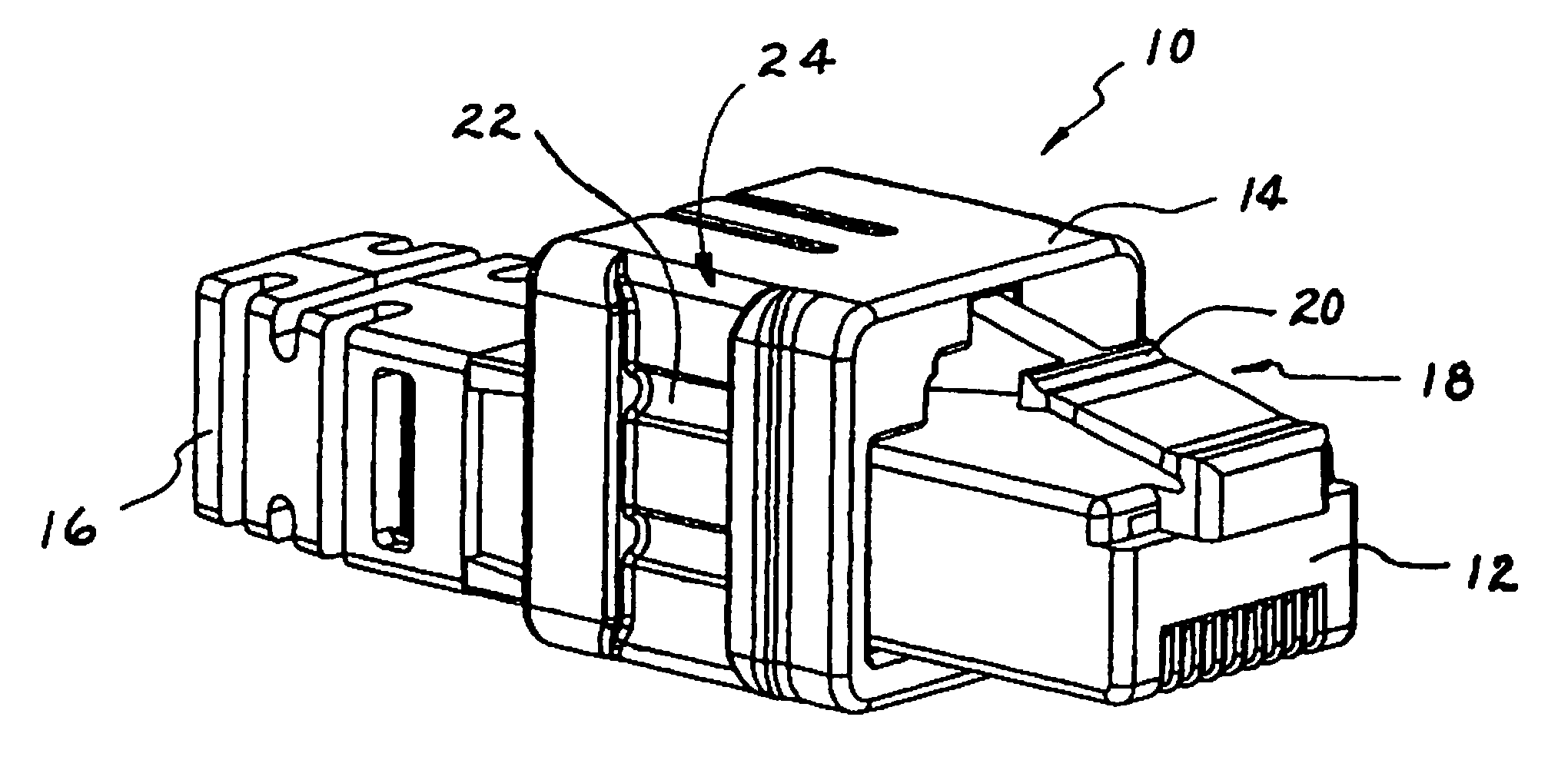
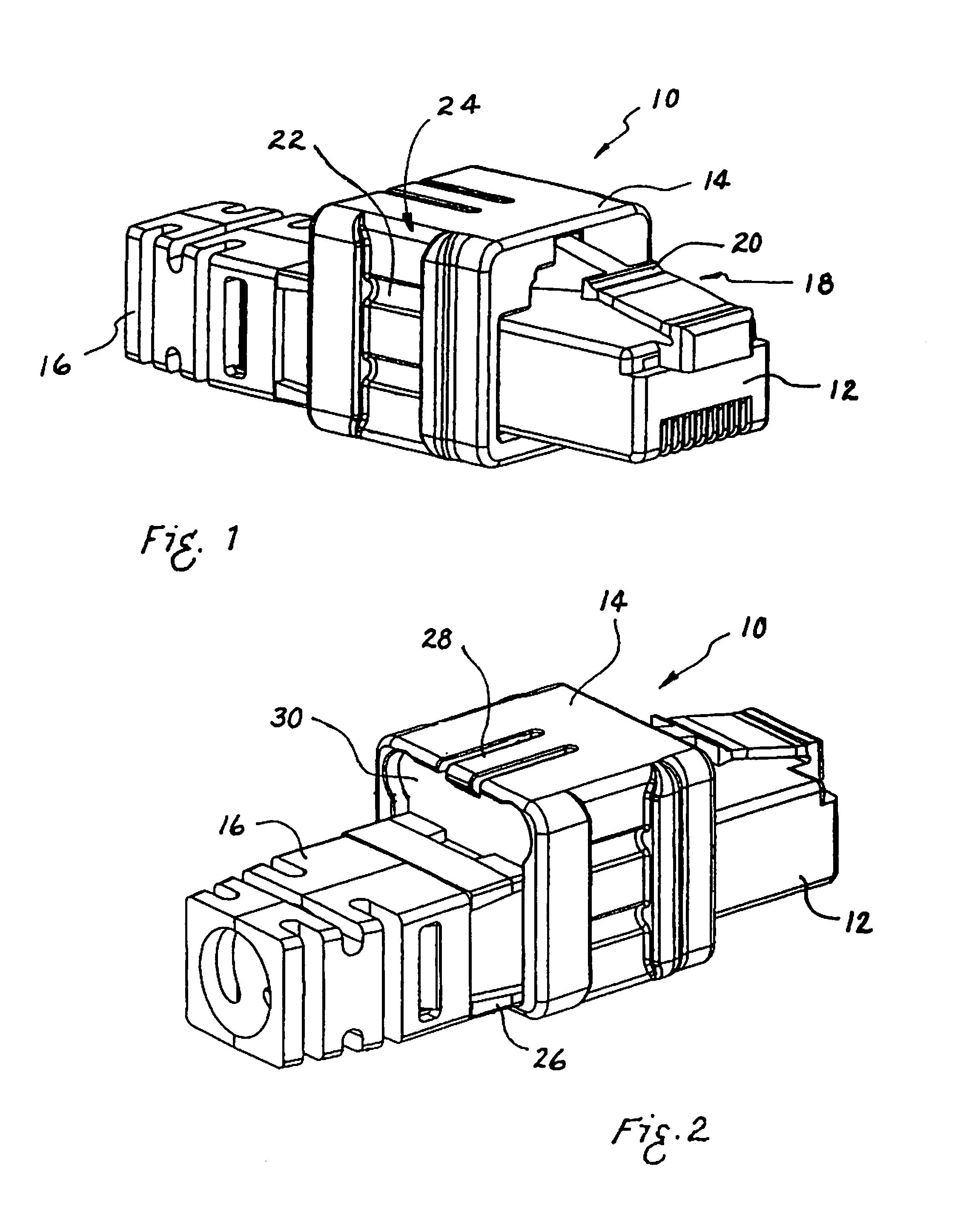
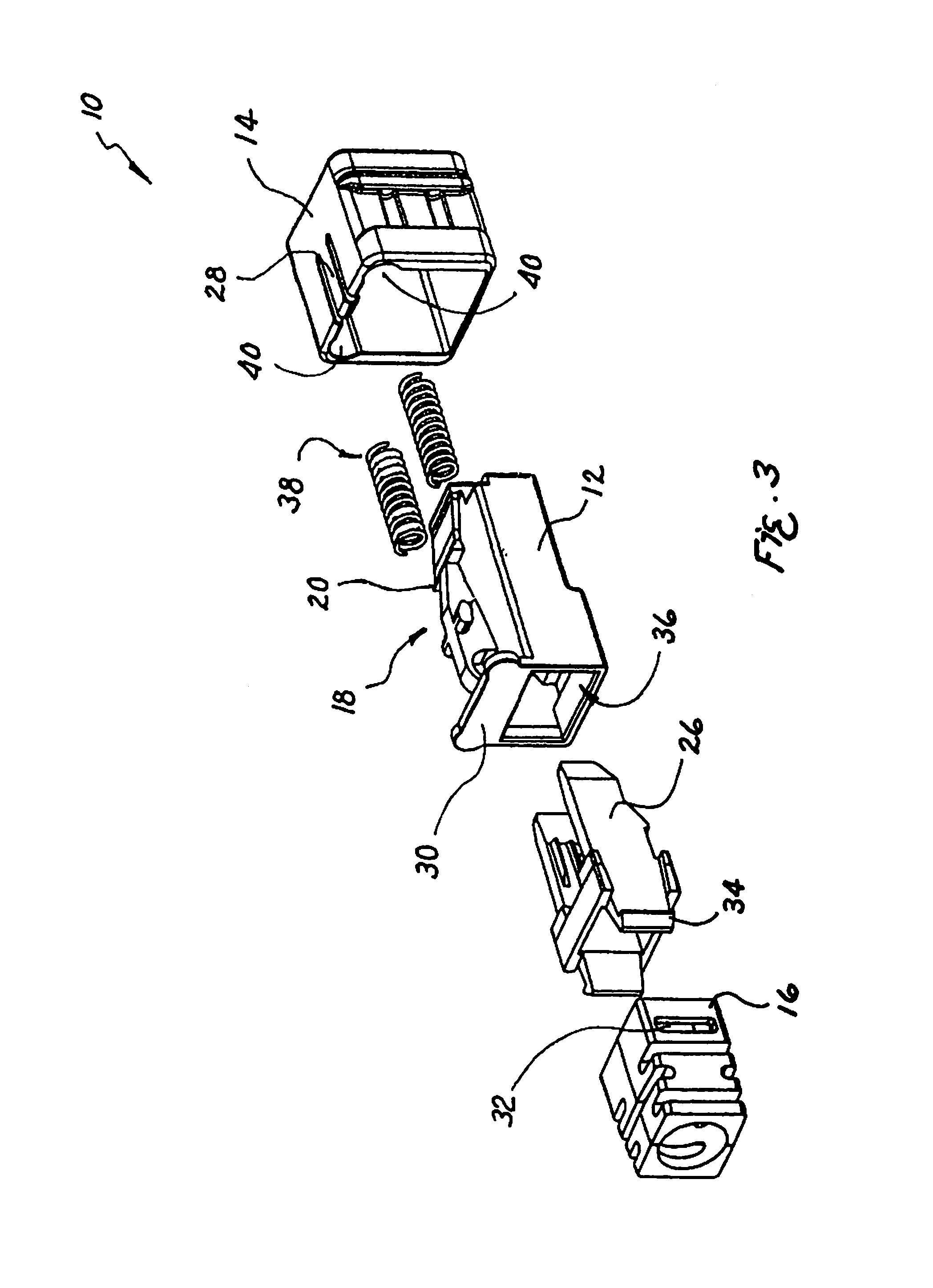
[0037]Turning now to FIG. 1, one embodiment of a plug 10 is shown. The plug 10 comprises a plug housing 12 and an outer housing 14. A boot 16 is attached to the rear of the plug housing 12 to control the bend radius of a cable 70 (shown in FIG. 27) terminated at the plug. The outer housing 14 interacts with a latch arm 18, shown in FIG. 3, moving a latch 20 of the latch arm between a first, or mated, position in which the latch is positioned to mate with a jack and a second, or unmated, position in which the latch is positioned to be released from a jack. The interaction between the outer housing 14 and the latch arm 18 allows the plug 10 to be installed and removed by pushing and pulling the outer housing 14. The boot 16 is connected to the plug at a boot adapter 26.

[0038]The outer housing 14 has retention notches 22 in retention grooves 24. The retention notches 22 and the retention grooves 24 allow a tool 52, shown in FIG. 10, to securely but releasably grip the outer housing 14 ...


PUM

PropertyMeasurementUnit
flexibleaaaaaaaaaa
cross-sectional shapeaaaaaaaaaa
densityaaaaaaaaaa

Abstract

A push-pull plug has an outer housing that may be moved forwardly and backwardly along a plug housing. When the outer housing is in its forward position, a latch arm is in an upward or mated position and the plug will stay mated to a jack when the plug is inserted into the jack. When the outer housing is moved backwardly, cam surfaces on the outer housing push cam followers on the latch arm downwardly, moving the latch arm and latch to a downward or unmated position. The plug may then be removed from a jack as the outer housing is pulled. The plugs may be adapted for use with an insertion and removal tool. Corner finger grips may be formed on the outer housing and may be located in an alternating manner to facilitate use when plugs are closely positioned.

Description

CROSS REFERENCE TO RELATED APPLICATION[0001]This application claims the benefit of U.S. Provisional Application No. 60 / 621,229 filed Oct. 22, 2004, and is incorporated herein by reference in its entirety.FIELD OF THE INVENTION[0002]The present invention relates generally to communications connectors and more particularly to push-pull plugs.BACKGROUND OF THE INVENTION[0003]With the rising importance of data communications, there is a drive toward the use of high-density connections. Increased density of connections in communications equipment—such as patch panels and network switches—is desirable because increased connection density allows for more connections in a given area. For example, many enterprises employ racks for their networking equipment, and the racks take up a certain amount of floor space. Such enterprises can install more network connections by replacing standard network equipment with high-density network equipment within the same racks. The high-density equipment th...

Claims


Application Information

Patent Timeline
Patent Type & Authority Patents(United States)
IPC IPC(8): H01R13/627
CPCH01R43/26H01R13/6272H01R13/562Y10T29/53283
Inventor CAVENEY, JACK E.HARTMAN, SCOTT R.DAVIS, DAVID R.
Owner PANDUIT
Why Eureka
Try Eureka