Hands-free breast pump with balanced reciprocating drive

a breast pump and hand-free technology, applied in the field of breast pumps, can solve the problems of pump failure, pump application of significant force, and pump failure, and achieve the effects of reducing noise, reducing the volume of the vacuum chamber, and reducing the amount of pump

Active Publication Date: 2008-11-06
MEDELA HLDG AG
View PDF6 Cites 66 Cited by
  • Summary
  • Abstract
  • Description
  • Claims
  • Application Information

AI Technical Summary

Benefits of technology

[0008]The present invention meets the needs described above in a second generation hands-free breast pump, referred to as the Gen-2 design, that includes a balanced push-pull vacuum generation system that applies pumping force to a bellows structure of a vacuum chamber formed by a breast interface cup during the inward and outward pump strokes. More specifically, the breast pump includes a breast cup that has a resilient bellows structure that partially collapses the volume of the vacuum chamber during the inward stroke and recovers the volume of the vacuum chamber during the outward stroke. The pump mechanism, which includes a cam drive system that translates rotary electric motor power into reciprocating linear action of an actuator arm that drives the bellows structure, applies force to the bellows structure during the inward pump stroke causing a reduction in the volume of the vacuum chamber and during the outward pump stroke causing an expansion of the volume of the vacuum chamber. The bellows structure acts like a spring that charges (resists the pump force) during the inward stroke and discharges (assists the pump force) during the outward stroke, and the shape of the cam track is designed to produce a desired operating profile for the pump. In addition, the shape of the cam track is carefully designed and fine tuned to produce a desired operating profile for the pump to mitigate motor current spikes, undue gear stress and reduce noise while producing a desired suck-release profile for the pump.
[0009]The use of a balanced drive system that applies force to the bellows structure of the breast cup during both the inward and outward pump strokes reduces the resiliency required of the bellows structure of the breast cup from that of the Gen-1 design, resulting in a more effective, efficient and user friendly hands-free breast pump design. For example, the Gen-2 pump running on a single AA battery achieves comparable suction levels at a comparable cycle rate when compared to the Gen-1 design running on two AA batteries. In addition, the reduced pumping force of the Gen-2 design allows this embodiment to achieve improved performance with a motor operating at significantly lower RMP and a significantly smaller gear ratio, which reduces the required number of gear meshes and allows for larger, more robust gears. These design improvements result in a lower cost, better performing, quieter and more robust breast pump that is easier to manufacture, easier to assemble, and has significantly fewer parts in the pump drive train. The Gen-2 pump also incorporates a number of other important design improvements, as described in more detail below. These additional features and advantages of the Gen-2 pump will become apparent to the skilled artisan upon examination of the following drawings and detailed description. It is intended that all such additional features and advantages be included within the scope of the present invention.

Problems solved by technology

As described above, the Gen-1 design utilizes an unbalanced pump mechanism that applies force to the vacuum chamber only during the inward stroke, whereas the resiliency of the bellows structure of the breast cup creates the suction during the outward stroke.
While this type of pump mechanism is highly functional, it requires application of a significant force to the breast cup during the inward stroke, which tends to urge the breast cup out of its seat within the breast pump housing.
Unless properly constrained, the force can be sufficient to cause the breast cup to pop out of its seat in the pump housing, which can cause the pump to malfunction.
Although the breast cup can be restrained within its seat in the housing using a suitable device, such as tabs, detent mechanisms or a support ring, these features add complexity and cost to the pump.
Perhaps more importantly, the additional breast cup restraining features make the pump more difficult to assemble with the breast cup properly seated within the pump housing.
Inevitably, a certain number of users are unable to assemble the pump correctly.
Unfortunately, the pump looks and sounds like it is working properly even when the breast cup is not seated properly, and the user can find it difficult to detect that the breast cup is not seated properly.
This gives some users who experience this problem the misimpression that the pump is assembled correctly and yet performs poorly, when the real problem is that the breast cup is not properly seated in the pump housing.
Apparent pump malfunction due to improper breast cup seating has, therefore, been a recurring problem with the Gen-1 design.
The unbalanced nature of the Gen-1 pump design (i.e., the application of motor force only during the inward stroke) also requires a relatively powerful pump motor to compress the bellows structure of the breast cup on the inward stroke against an amount of natural resiliency of the silicon that is sufficient to generate the desired suction within the breast cup on the outward stroke.
Pumping against this amount of spring force on the inward stoke, without the assistance of the motor on the outward stroke, is inefficient because the motor is used in an unbalanced manner in that high force is applied from the motor on the inward stroke, whereas no force is applied by the motor on the outward stroke.
This unbalanced pump design requires higher power, reduces the cycle rate, taxes the motor, and stresses the internal gear train components to a higher degree than could be obtained from a more balanced design.

Method used


Image

  • Hands-free breast pump with balanced reciprocating drive
  • Hands-free breast pump with balanced reciprocating drive
  • Hands-free breast pump with balanced reciprocating drive

Examples


Embodiment Construction

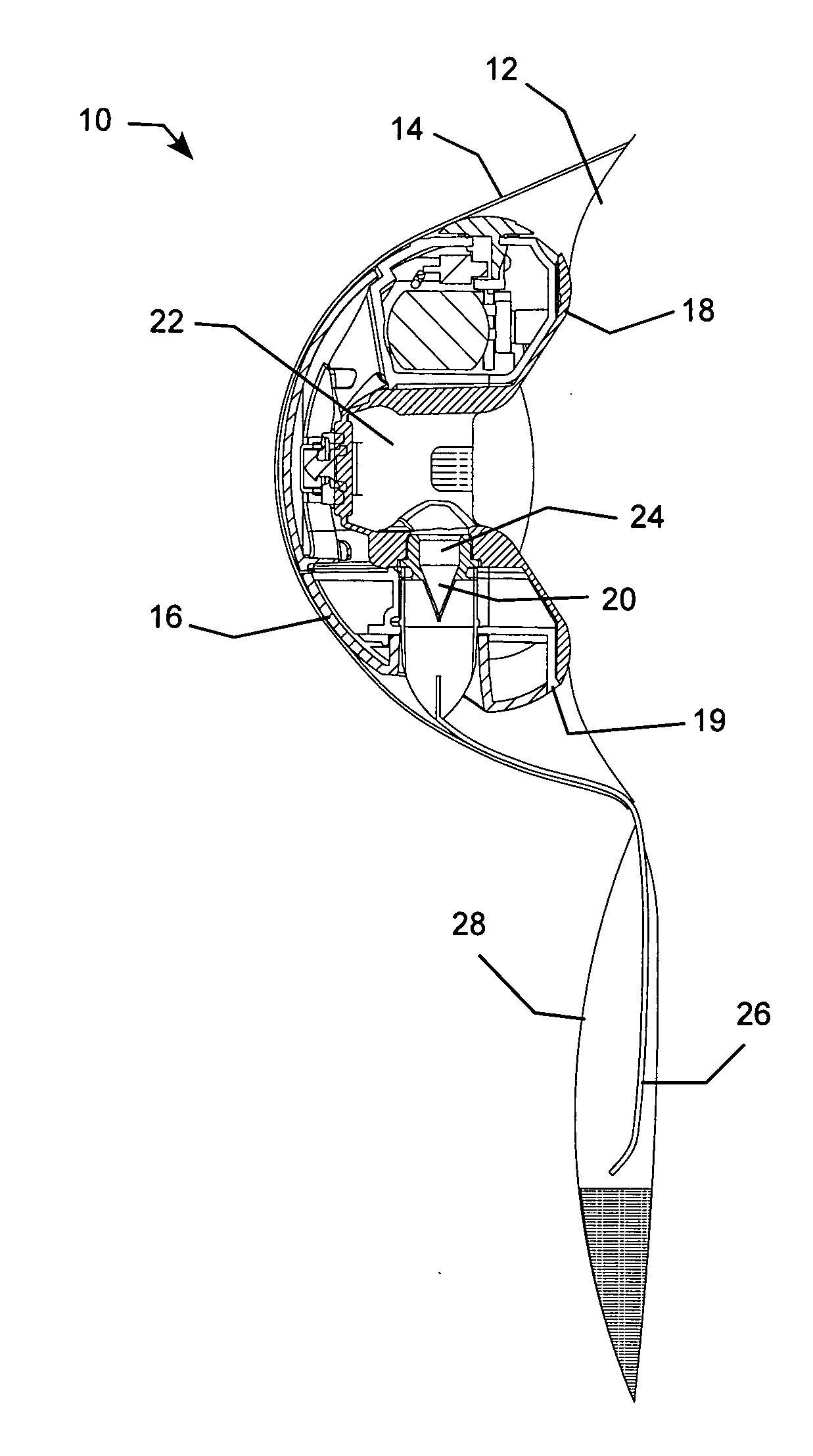
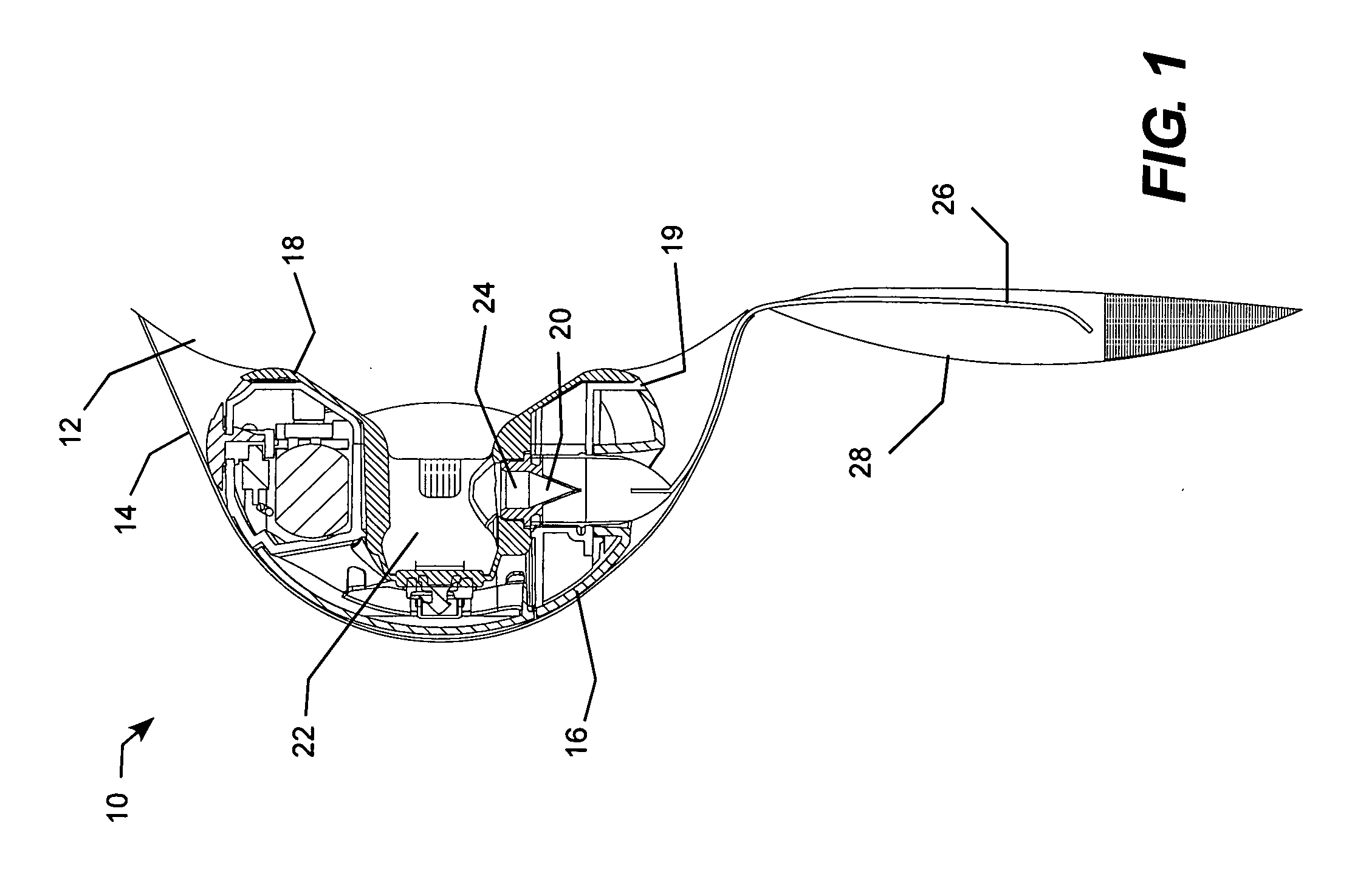
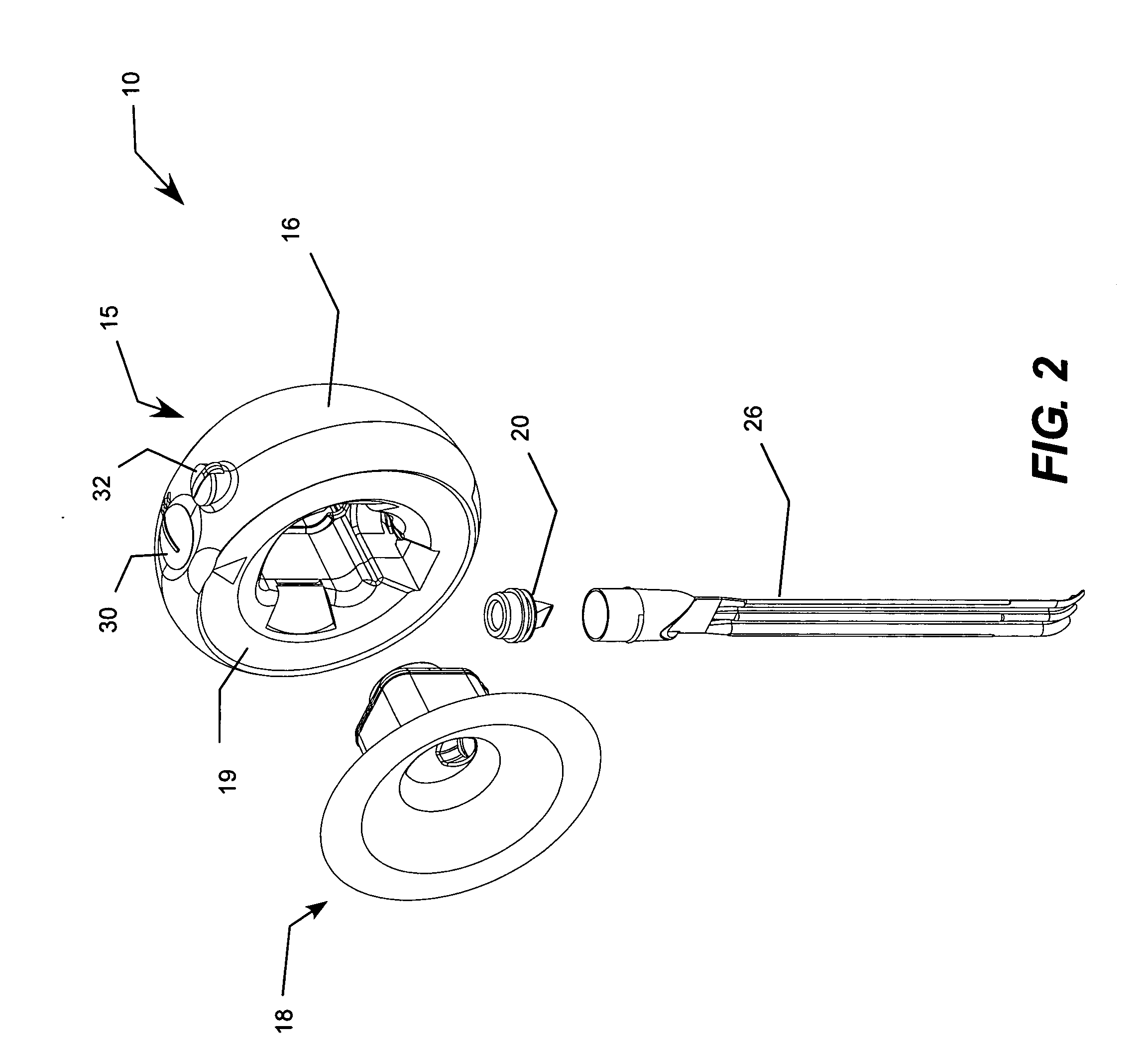
[0039]The present invention may be embodied in a hands-free breast pump with a balanced push-pull mechanical actuator and cam drive system that applies pumping force to a bellows structure of a breast interface cup during inward and outward pump strokes. As the Gen-1 design applied no motor force to the bellows structure on the outward pump stroke, configuring the Gen-2 pump to apply any amount of motor force to the bellows structure during both the inward (push) and outward (pull) strokes achieves some level of balance in the drive system and therefore improves the balance over the Gen-1 design. Significant attention has been paid to this design feature in the Gen-2 pump, which achieves a relatively high level of balance, for example where the force applied by the pump during the inward stroke is within eighty percent (80%) of the force applied during the outward stroke. In the particular embodiment shown in the figures and described below, the Gen-2 pump is well optimized to achie...


PUM


Abstract

A hands-free breast pump that includes a balanced push-pull reciprocating drive system that applies pumping force to a vacuum chamber formed by a breast interface cup during inward and outward pump strokes. The breast pump includes a breast cup that has a resilient bellows structure that partially collapses the volume of the vacuum chamber during the inward stroke and recovers the volume of the vacuum chamber during the outward stroke. The pump mechanism includes a cam drive system that translates rotary electric motor power into reciprocating linear action of an actuator arm that drives the bellows structure. The bellows structure acts like a spring that charges (resists the pump force) during the inward stroke and discharges (assists the pump force) during the outward stroke, and the shape of the cam track is designed to produce a desired operating profile for the pump.

Description

REFERENCE TO RELATED APPLICATION[0001]This application claims priority to U.S. Provisional Patent Application Ser. No. 60 / 915,937 filed May 4, 2007 entitled “Hands-Free Breast Pump with Balanced Reciprocating Drive,” which is incorporated herein by reference.TECHNICAL FIELD[0002]The present invention is generally related to breast pumps that cause nursing mothers to express breast milk and, more particularly, to a hands-free breast pump with a balanced push-pull vacuum generation system that applies pumping force to a bellows structure of a vacuum chamber formed by a breast interface cup during inward and outward pump strokes.BACKGROUND OF THE INVENTION[0003]The first hands-free breast pump including a self-contained pump mechanism and power source configured to be held in place between a nursing mother's breast and bra is described in U.S. Pat. No. 7,223,255 entitled “System For a Portable, Hands-Free Breast Pump and Method of Using the Same,” which is incorporated herein by refere...

Claims


Application Information

Patent Timeline
Patent Type & Authority Applications(United States)
IPC IPC(8): A61M1/06
CPCA61M1/06A61M2205/8206A61M1/064A61M1/0068A61M2209/088A61M1/062A61M1/81A61M1/067A61M1/0697
Inventor MYERS, KENNETH E.
Owner MEDELA HLDG AG
Why Eureka
Try Eureka