Cover for pressure cooker with locking pieces

a technology of pressure cooker and locking piece, applied in the field of pressure cooker cover, can solve problems such as trouble for users

Active Publication Date: 2015-03-10
HE ZHIGANG +1
View PDF12 Cites 71 Cited by
  • Summary
  • Abstract
  • Description
  • Claims
  • Application Information

AI Technical Summary

Problems solved by technology

The disadvantage of the structure is that the float can move up under external force whether the pressure in the cooker body is sufficient or whether the cooker cover is open, thus causing trouble to users.

Method used


Image

  • Cover for pressure cooker with locking pieces
  • Cover for pressure cooker with locking pieces
  • Cover for pressure cooker with locking pieces

Examples


Embodiment Construction

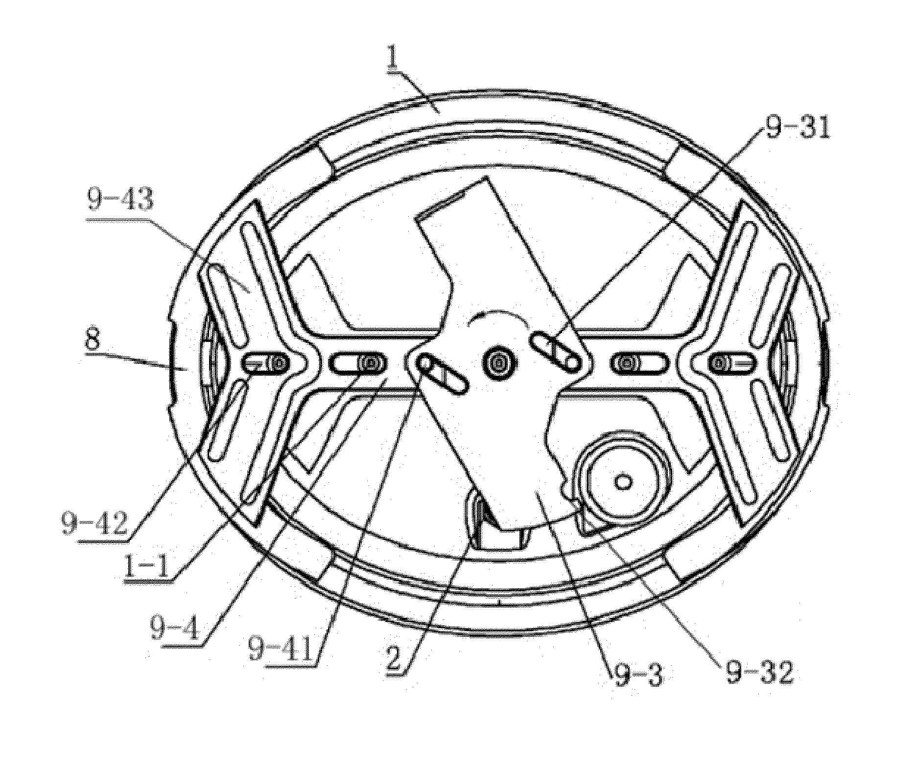
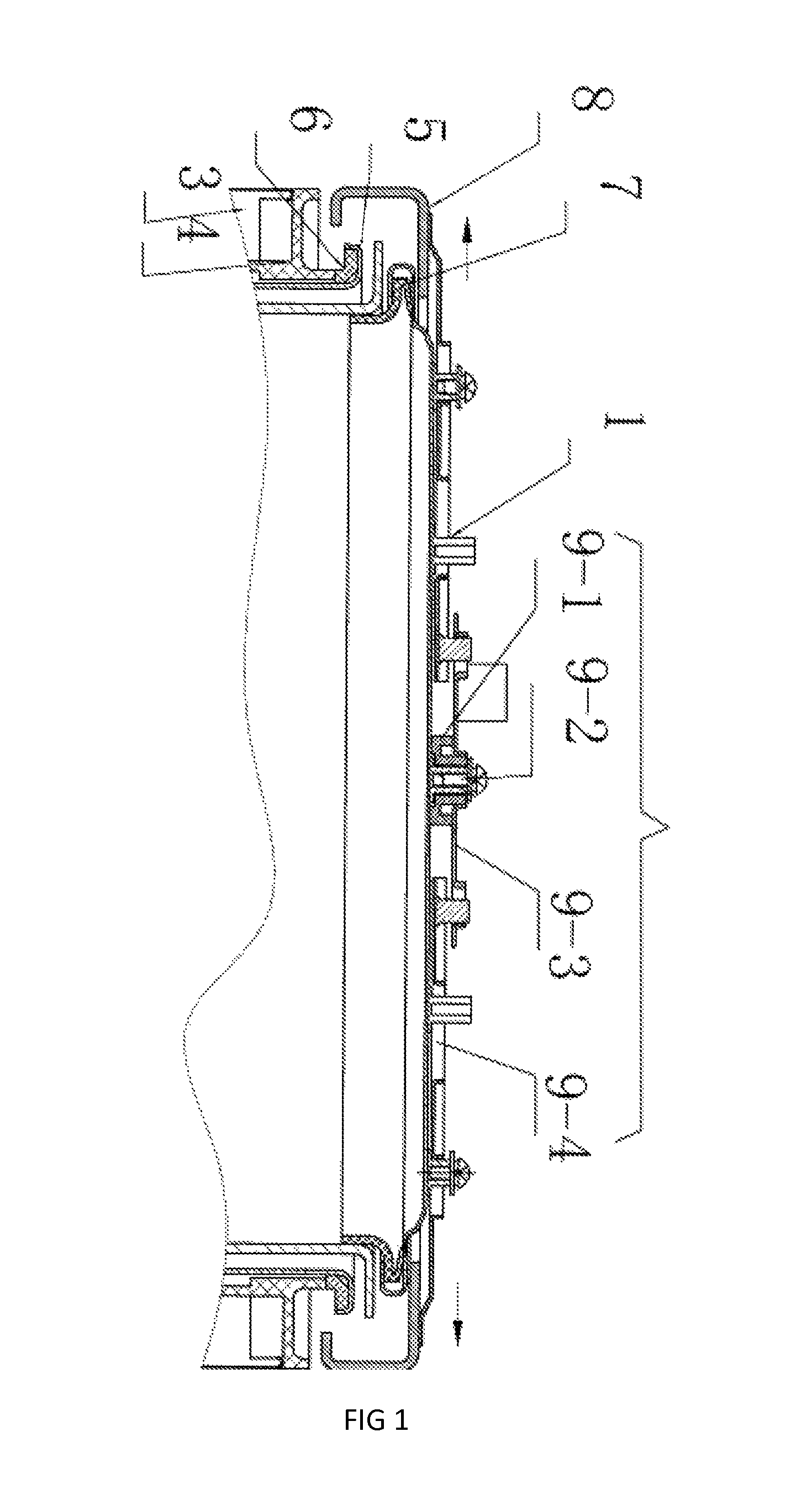
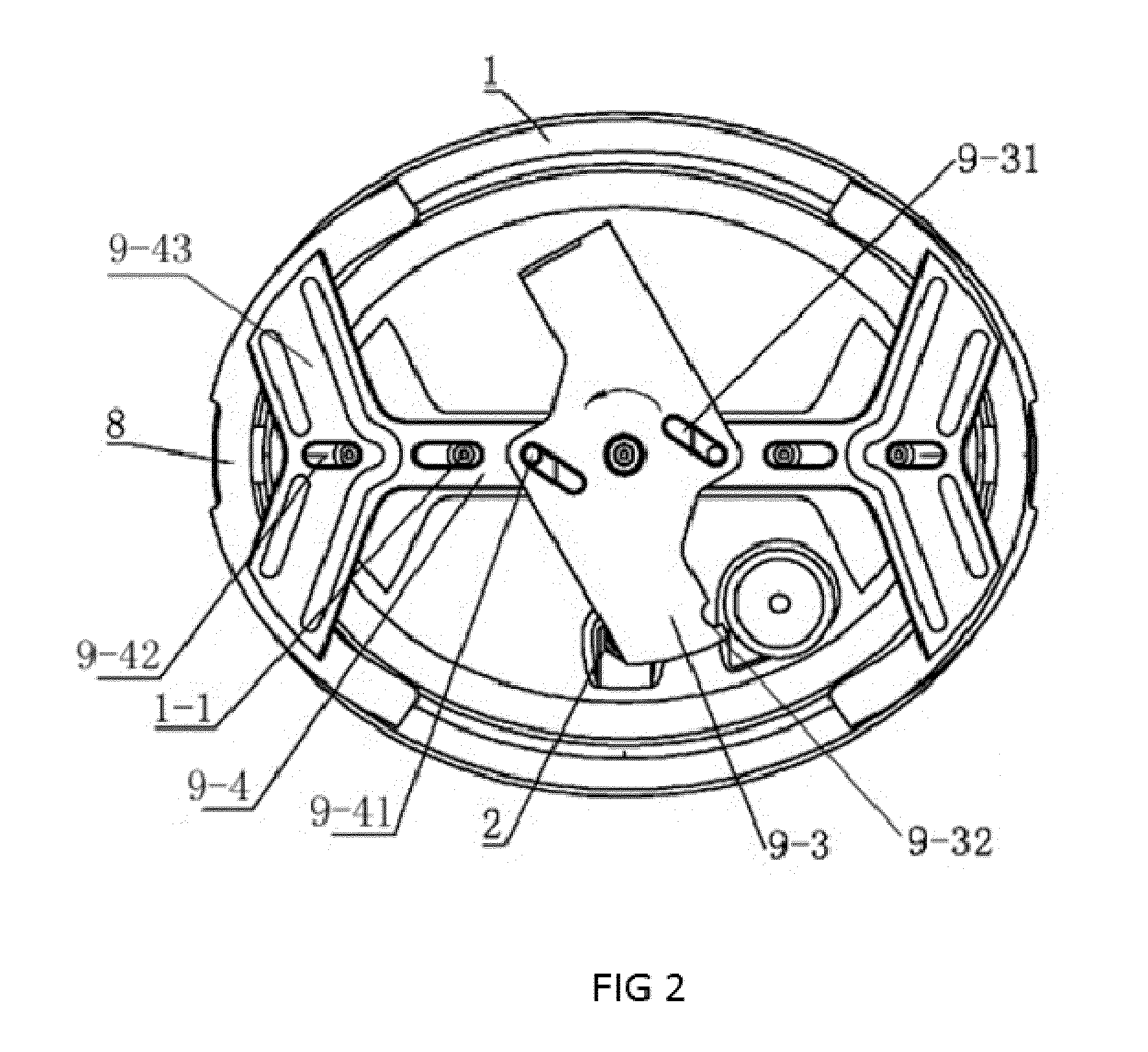
[0018]As illustrated in FIGS. 1-4, a pressure cooker cover, comprising a cover 1, a float valve 2, a seal ring 7, hooks 8 and a push-pull device 9.

[0019]The said float valve 2 is installed at the inner edge of the cover 1 and can penetrate through the cover 1 from the top to bottom of the cover 1. The seal ring 7 is set at the inner edge of the cover 1. There are two hooks 8, which are symmetrically installed at the edge of the cover 1, the two hooks are arranged at 180 degree from each other around the edge of the circumference of the cover. The said push-pull device 9 comprises a rotating base 9-1, a rotating shaft 9-2, a locking piece 9-3 and two sliding bars 9-4. The rotating base 9-1 is installed in the center of the cover 1, the rotating shaft 9-2 is installed on the rotating base 9-1, the locking piece 9-3 is coupled with the rotating shaft 9-2; each one end of two sliding bars 9-4 is respectively connected with the locking piece 9-3, each another end of two sliding bars 9-4 ...


PUM


Abstract

A pressure cooker cover comprises a cover (1) and a float valve (2), wherein a seal ring (7) is installed in the inner edge of the cover while hooks (8) are installed in the two side edges of the cover. A push-pull device (9) which can move the hooks back and forth is mounted in the ends of the hooks. The push-pull device comprises a rotating base (9-1) arranged in the middle portion of the cover, a rotating shaft (9-2) and a locking piece (9-3) which is coupled with the rotating shaft (9-2). Sliding chutes (9-31) are provided at the two sides of the locking piece. Guide columns (8-1) which are slidingly matched with the sliding chutes are set at two ends of the hooks (8).

Description

[0001]This application is a continuation-in-part application of U.S. patent application Ser. No. 13 / 825,967 filed Mar. 25, 2013, which is the U.S. national phase of International Application No. PCT / CN2010 / 078628 Filed 11 Nov. 2010 which designated the U.S. and claims priority to Chinese Application Nos. 201020547421.3 filed 28 Sep. 2010, the entire contents of each of which are hereby incorporated by reference.TECHNICAL FIELD[0002]The invention relates to the technical field of pressure cooker, particularly to a pressure cooker cover.BACKGROUND ART[0003]With the continuous improvement of people's living standard, pressure cooker gains increasing popularity among people for its convenient use, environmental protection and energy saving. In respect of the structure, it mainly comprises a shell, a cooker cover and a cooker body, wherein a float valve, a pressure relief valve and a safety valve are provided on the cooker cover; when the pressure in the cooker body rises to a certain le...

Claims


Application Information

Patent Timeline
Patent Type & Authority Patents(United States)
IPC IPC(8): A47J27/08B65D45/16
CPCA47J27/0804B65D45/16
Inventor HE, ZHIGANGHUANG, ZHIBIN
Owner HE ZHIGANG
Why Eureka
Try Eureka