DC-DC converter with improved dynamic response

a dc-dc converter and dynamic response technology, applied in the direction of automatic control, process and machine control, instruments, etc., can solve the problems of inability to achieve the dynamic response the efficiency of the converter is eventually reduced to an unacceptable level, and the design of the converter is complicated, etc., to achieve the effect of improving the dynamic performance of a dc-dc converter

a dc-dc converter and dynamic response technology, applied in the direction of automatic control, process and machine control, instruments, etc., can solve the problems of inability to achieve the dynamic response the efficiency of the converter is eventually reduced to an unacceptable level, and the design of the converter is complicated, etc., to achieve the effect of improving the dynamic performance of a dc-dc converter

US20080258701A1Active Publication Date: 2008-10-23GANPOWER SEMICON FOSHAN LTD

Image

  • DC-DC converter with improved dynamic response
  • DC-DC converter with improved dynamic response
  • DC-DC converter with improved dynamic response

Examples


example 1

Charge Balance Auxiliary Branch Controller

[0138]The principle of capacitor charge balance may be used to ensure that the output voltage and the inductor current reach steady state simultaneously and in the minimum possible time. FIG. 14 shows the transient response to a negative current step under the proposed control method.

[0139]It is observed in FIG. 14 that the capacitor charge portion Acharge may now be approximated by equation (21).

Acharge=∫t0t1a[iL(t)-iaux_avg-io2]t(21)

[0140]Thus Acharge, and subsequently the voltage overshoot, is significantly reduced due to the current in the auxiliary branch. It is apparent in FIG. 14 that the topology can be controlled effectively by the abovementioned control method with minor modifications. In order for the control method to function correctly, it must detect the crossover point of iL−iaux—avg−io, and the crossover point of iL−io. At t1b, when the iL−io crossover point is detected, the auxiliary circuit is disabled; however, the duty cy...

example 2

Simplified Auxiliary Branch Controller

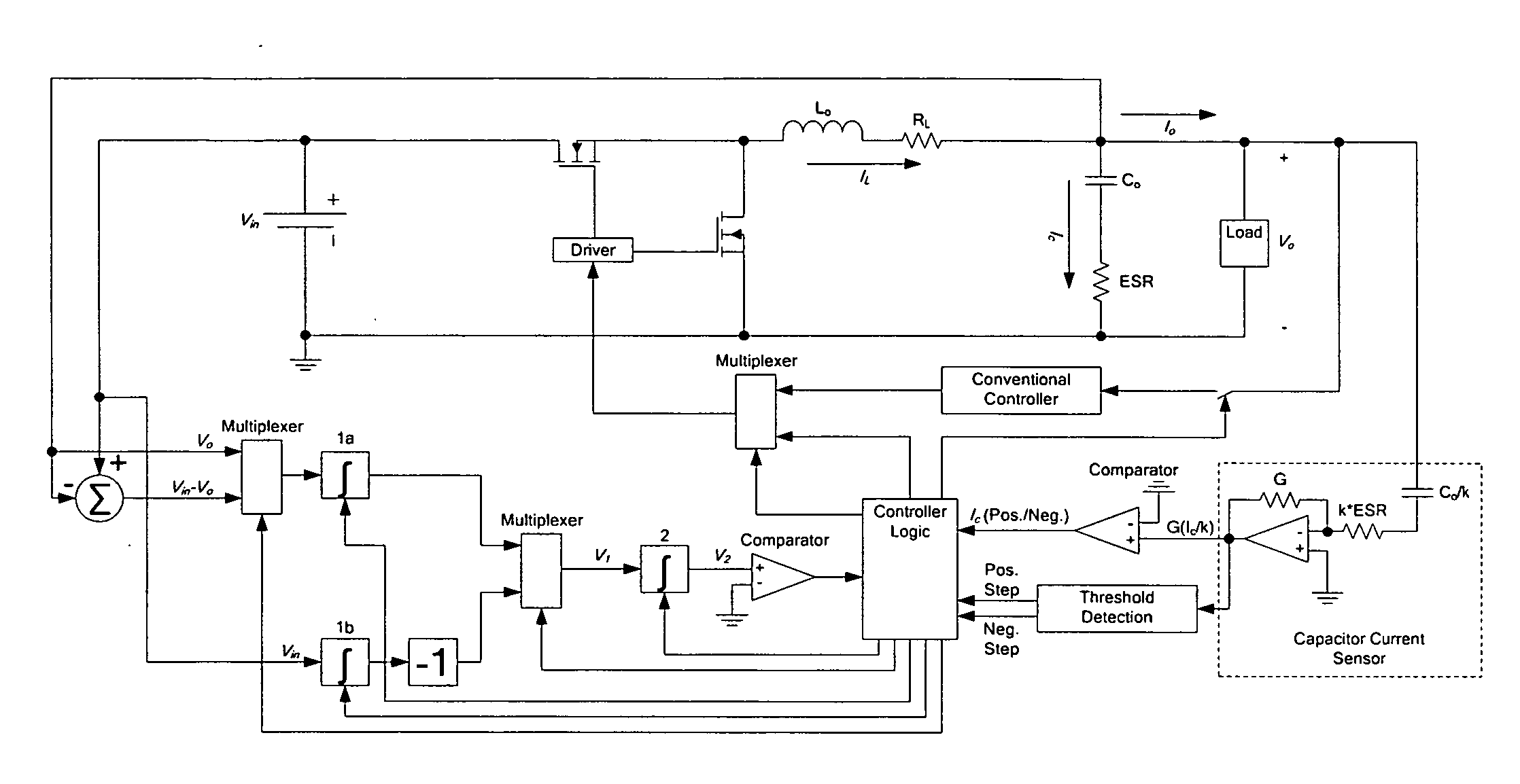
[0144]The above-mentioned controller may be greatly simplified by slightly sacrificing settling time. The simplified controller functions similarly to the controllers described above; however, it does not employ charge balance techniques, and at the point when the inductor current equals the new load current, the auxiliary branch is disabled and the control is returned to the conventional controller (e.g., voltage mode, current mode, or hysteresis mode controller). This method eliminates the need for integrators or an extra comparator. FIGS. 18(a) and (b) show block diagrams of two embodiments of such a simplified controller. In FIG. 18(a), connections shown in dashed lines are optional.

[0145]To reduce the impact of high frequency output voltage ripple caused by the equivalent series inductance (ESL) of the output capacitor, a low-pass filter (with corner frequency set below the auxiliary switching frequency) may be placed at the output of the a...

example 3

Auxiliary Branch Controller with Variable Auxiliary Current

[0158]To prevent a voltage undershoot after the initial voltage overshoot, the auxiliary current may be controlled as shown in FIG. 19. This method eliminates the possibility of a voltage undershoot at the expense of settling time. As shown in FIG. 19, at time t1, the auxiliary current level is reduced such that it equals iL−io2. The auxiliary current level may be varied by controlling the auxiliary current reference with the output of the capacitor current sensor. This operation causes the output voltage to be relatively constant for time period t1 to t2. At time t2, the conventional controller resumes control.


PUM


Abstract

The invention relates to a control method and a controller for a DC-DC converter, such as a synchronous Buck converter, which exploits the principle of capacitor charge balance to allow the converter to recover from a positive and / or negative load current step in the shortest achievable time, with the lowest possible voltage undershoot / overshoot. The control method may be implemented by either an analog or a digital circuit. The controller may be integrated with existing controller schemes (such as voltage-mode controllers) to provide superior dynamic performance during large-signal transient conditions while providing stable operation during steady state conditions. The invention also relates to a method and a modification of a DC-DC converter topology that comprises connecting a controlled current source between an input terminal and an output terminal of the DC-DC converter; detecting a load current step to a new load current; modifying a duty cycle of the DC-DC converter; and modifying current through a parallel output capacitor of the DC-DC converter by controlling current of the current source. The methods and circuits provided herein are applicable to Buck converters and Buck-derived converters such as forward, push-pull, half-bridge, and full-bridge converters.

Description

RELATED APPLICATIONS[0001]This application claims the benefit of the filing date of U.S. Provisional Patent Application No. 60 / 907,794, filed on Apr. 17, 2007, the contents of which are incorporated herein by reference in their entirety.FIELD OF THE INVENTION[0002]This invention relates to methods and circuits for improving the dynamic response of a DC-DC converter to a load current step. The methods and circuits relate to controllers for DC-DC converters and to DC-DC converter topology.BACKGROUND OF THE INVENTION[0003]As voltage regulation criteria for digital circuits such as CPUs become more stringent, the demand for high dynamic performance power converters increases. Among the many characteristics of dynamic performance, output voltage overshoot / undershoot and recovery time are often considered the most important. In general, the output voltage deviates under load current change, or input voltage change. To improve the dynamic response of a DC-DC converter, the switching freque...

Claims


Application Information

Patent Timeline
23 Oct 2008
Publication
US20080258701A1
IPC
H02J1/00
CPC
H02M3/1588; Y02B70/1466; Y02B70/10
Inventors
LIU, YAN-FEI; MEYER, ERIC