Sheet storage device for image forming apparatus

a technology of image forming apparatus and storage device, which is applied in the direction of pile receivers, transportation and packaging, thin material processing, etc., can solve the problems of operator danger, and achieve the effect of improving the alignment performance of discharge sheets

Inactive Publication Date: 2007-11-27
RICOH KK
View PDF6 Cites 21 Cited by
  • Summary
  • Abstract
  • Description
  • Claims
  • Application Information

AI Technical Summary

Benefits of technology

[0010]It is an object of the present invention to provide a sheet storage device in which, when the leading edge of a sheet discharged from the outlet of an image forming apparatus collides with an end fence, the sheet is prevented from rebounding toward the outlet owing to an appropriate shaping of a shock absorber, so that an improvement in discharge sheet alignment performance is improved.
[0011]It is another object of the present invention to provide a sheet storage device in which, when a sheet having collided with an end fence is stacked on a sheet discharge table, the sheet is prevented from sneaking through the gap between the lower portion of the end fence and the upper surface of the sheet discharge table, and the operator's safety can be maintained.

Problems solved by technology

(1) A construction having a fence member provided upright on a sheet discharge table and a shock absorber mounted on the discharged sheet receiving surface side of the fence member with a gap between the shock absorber member and the delivery sheet receiving surface. The upper end of the shock absorber is supported in a manner as to be vertically movable and the lower end is fixed to the fence member. This construction is disclosed, for example, in JP 11-217151. In this prior art technique, a plate-like shock absorber such as a sponge member is provided on the front side of the fence member (the upstream side with respect to the sheet transport direction). The lower end portion of the shock absorber is fixed to the fence member by adhesive or the like, the upper side thereof is curved into a concave shape, and the upper end portion is held with clearance by an engagement portion formed in the upper portion of the fence member. Therefore, a gap between the fence member and the shock absorber is formed. Since the upper end portion of the shock absorber is held with clearance by the engagement portion of the fence member, it can be vertically displaced. Thus, when discharged sheets are stacked on the discharge table and the upper end portion of the shock absorber is downwardly displaced, there is little reduction in the change of the amount of gap between the fence member and the shock absorber at the sheet colliding position, with the result that the impact at the time of sheet collision is absorbed.
(2) A technique for preventing a sheet from sneaking through a gap between the lower portion of the fence member and the upper surface of the sheet discharge table, in which a “leg” extends from the lower portion of the fence member and a groove is formed in the upper surface of the sheet discharge table, causing the lower portion of the fence member to cross the upper surface of the sheet discharge table.
In the prior art technique (2), when the fence member is positioned as it is at the sheet receiving position, it causes an obstacle at the time of removing the sheets stacked on the sheet discharge table.
That is, when the support arm is rotated to cause the fence member and the shock absorber to integrally retract from the sheet removal area and to set them to the original positions again, there may be a danger of the operator such that his hand is caught between the above-mentioned “leg” and the upper surface portion of the sheet discharge table so as to suffer injury.

Method used


Image

  • Sheet storage device for image forming apparatus
  • Sheet storage device for image forming apparatus
  • Sheet storage device for image forming apparatus

Examples


Embodiment Construction

[0024]The present invention will now be described in detail with reference to the drawings.

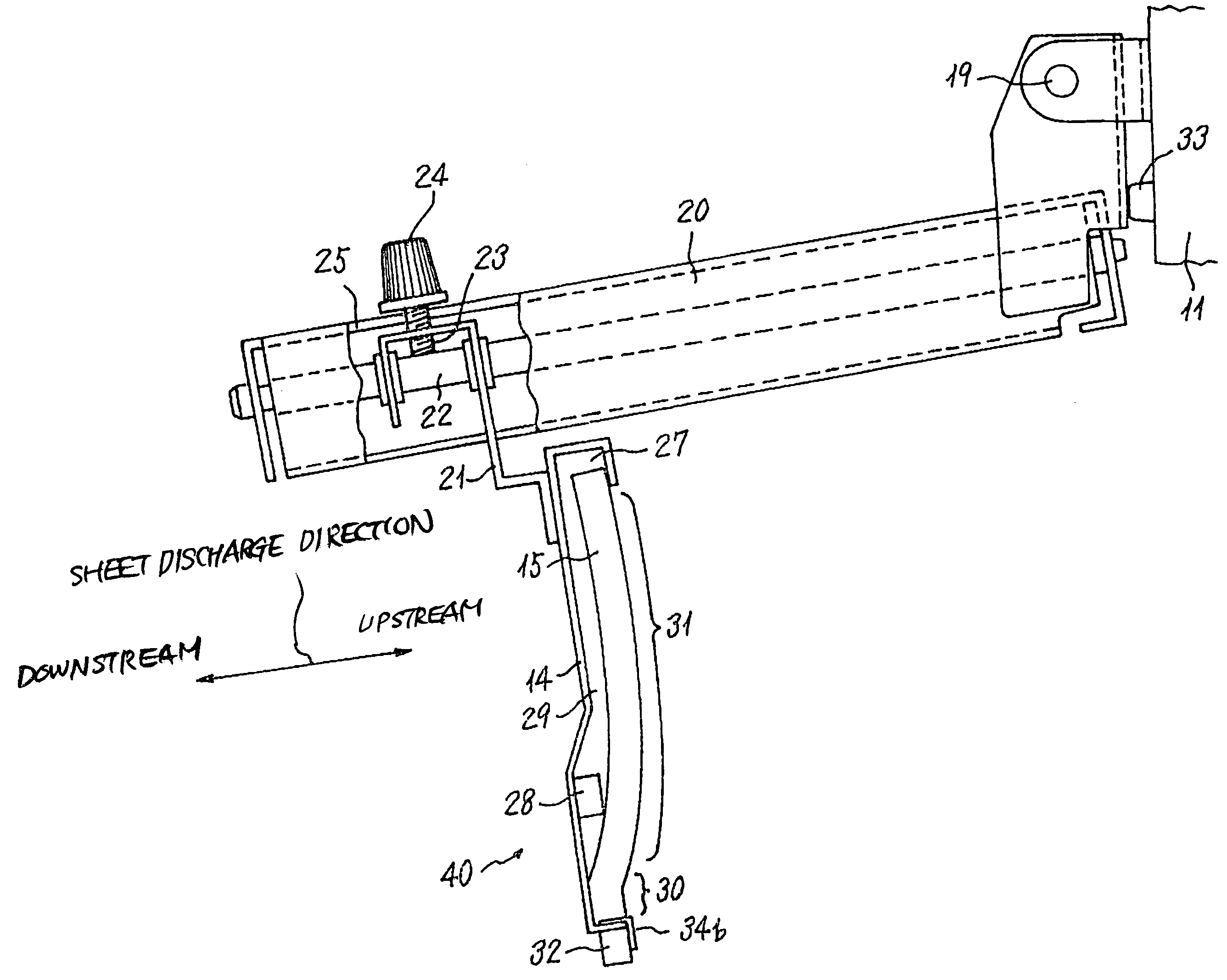
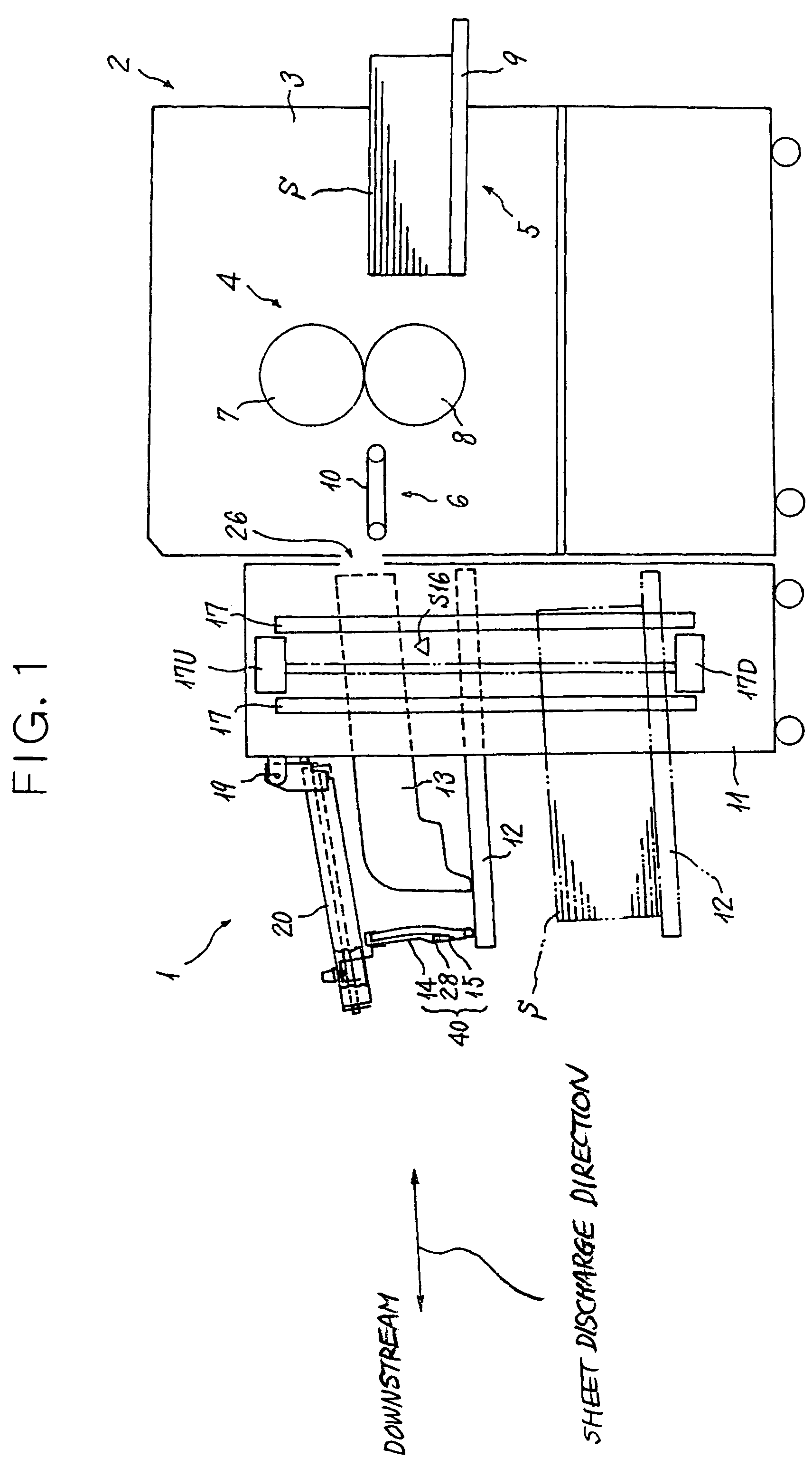
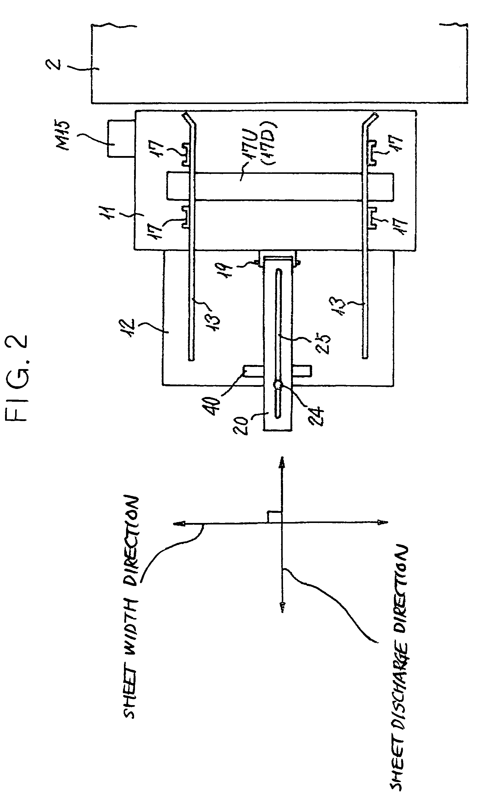
[0025]FIGS. 1 through 3 show the construction of a stencil printer 2 as an image forming apparatus and a sheet storage device 1 in accordance with an embodiment of the present invention.

[0026]The stencil printer 2 comprises a casing 3, a printing section 4 provided substantially at the center of the casing 3, and a sheet feeding section 5 provided on the right-hand side of the casing 3 and a sheet discharge section 6 provided on the left-hand side of the casing 3. The printing section 4 has a print drum 7 rotatable with a perforated stencil or master wrapped therearound, and a press roller 8 which rotates in synchronism with the print drum 7 and brings a sheet S into press contact with the print drum 7. The sheet feeding section 5 has a sheet feeding tray 9 on which sheets S are stacked together, and a sheet feeding mechanism (not shown) for feeding sheets S from the sheet feeding tray 9 to th...


PUM


Abstract

A sheet storage device improved in terms of its performance in aligning sheets discharged from an image forming apparatus. In the sheet storage device, a plate-like shock absorber is superimposed on a surface of a fence member forming an end fence, and a lower end portion of the shock absorber is fixed to the fence member, with an intermediate portion thereof being curved so as to be convex and an upper end portion thereof being movably engaged with an engagement portion formed at an upper end of the fence member. In the intermediate portion, a spacer is provided between the fence member and the shock absorber to form a gap between the shock absorber and the fence member at a position where the shock absorber is hit by the sheets.

Description

BACKGROUND OF THE INVENTION[0001]1. Field of the Invention[0002]The present invention relates to a sheet storage device for stacking sheets discharge from an outlet of an image forming apparatus in order or in a regular manner on a sheet discharge table.[0003]2. Description of the Background Art[0004]Conventionally, the following prior art techniques relating to a sheet discharge device of this type mentioned above are known:[0005](1) A construction having a fence member provided upright on a sheet discharge table and a shock absorber mounted on the discharged sheet receiving surface side of the fence member with a gap between the shock absorber member and the delivery sheet receiving surface. The upper end of the shock absorber is supported in a manner as to be vertically movable and the lower end is fixed to the fence member. This construction is disclosed, for example, in JP 11-217151. In this prior art technique, a plate-like shock absorber such as a sponge member is provided on...

Claims


Application Information

Patent Timeline
Patent Type & Authority Patents(United States)
IPC IPC(8): B65H31/20B65H31/36B65H31/34
CPCB65H31/34B65H2403/60B65H2511/11B65H2220/01B65H2220/04
Inventor ASANO, YUKIHIRO
Owner RICOH KK
Why Eureka
Try Eureka