Board securing device

a technology for securing devices and motherboards, applied in the direction of coupling device connections, coupling parts engagement/disengagement, support structure mounting, etc., can solve the problems of restricted shaking or swinging in the horizontal restricted shaking or swinging in the vertical direction relative to the motherboard, so as to prevent damage

Inactive Publication Date: 2007-11-27
FRAMATOME CONNECTORS INT SA
View PDF44 Cites 54 Cited by
  • Summary
  • Abstract
  • Description
  • Claims
  • Application Information

AI Technical Summary

Benefits of technology

[0007]protruding portions provided in the vicinity of both ends of the base portion, preventing said printed circuit board from being lifted up when the printed circuit board is fixed, by covering the vicinity of both end portions of an edge portion of the printed circuit board;
[0030]For example, by providing a stopper for preventing excessive elastic deformation of the base portion, at a certain distance in the elastic deformation direction of the said base portion, a pressing force of greater than a certain amount would never be exerted from the said printed circuit board, so that breakage of the base portion due to overloading can be prevented.

Problems solved by technology

Thereby, shaking or swinging in the horizontal direction relative to the motherboard is restricted due to the stabilizing piece, and shaking or swinging in the vertical direction relative to the motherboard is restricted due to the engaging of the said protruding portions of the base portion and the said other end portion of the printed circuit board.

Method used


Image

  • Board securing device
  • Board securing device
  • Board securing device

Examples


embodiment 1

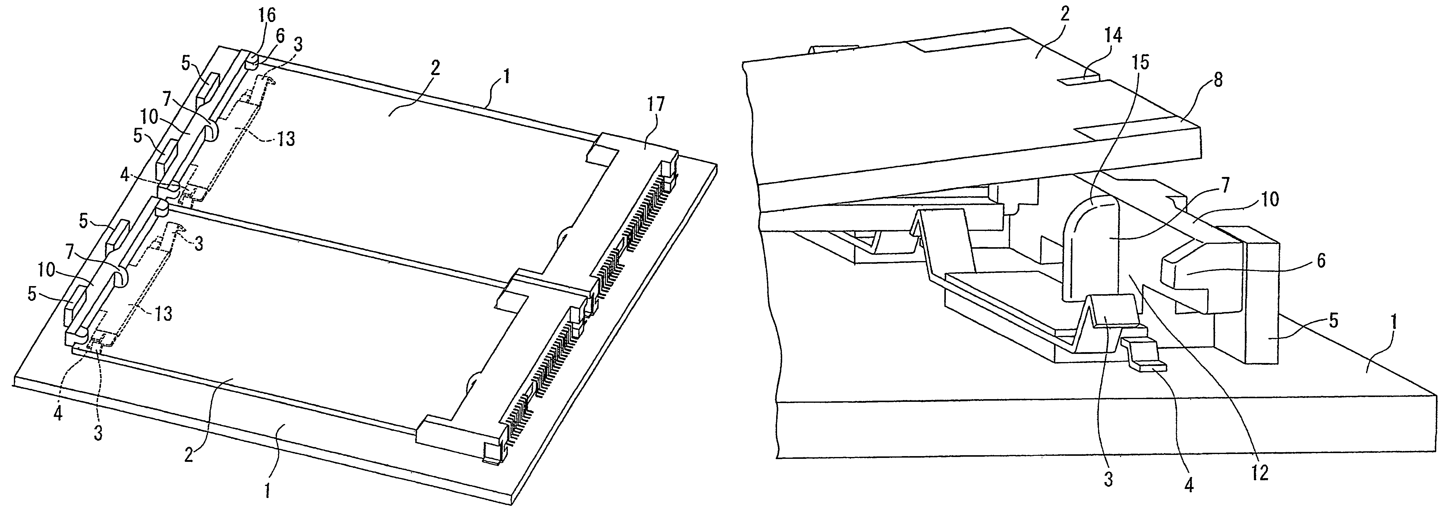
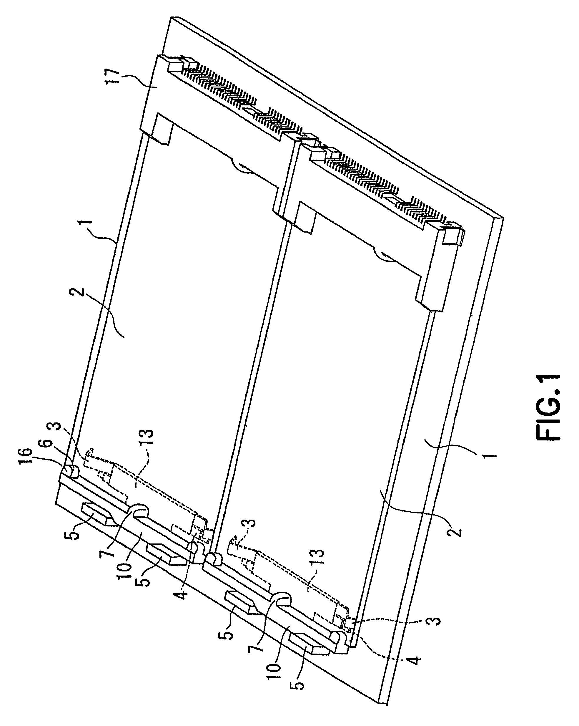
[0074]FIG. 1 is an external view of when a printed circuit board 2 is completely fixed to a dual socket fixed-type motherboard 1 whereon the fixing device of the present application is placed, by rotating one end of said printed circuit board 2, in a connector 17 having spring contacts forming a contact row in a direction perpendicular to the board insertion direction, during the insertion of the printed circuit board 2 into said connector 17, while making contact with the said spring contacts, in a direction whereby the spring contacts are pressed.

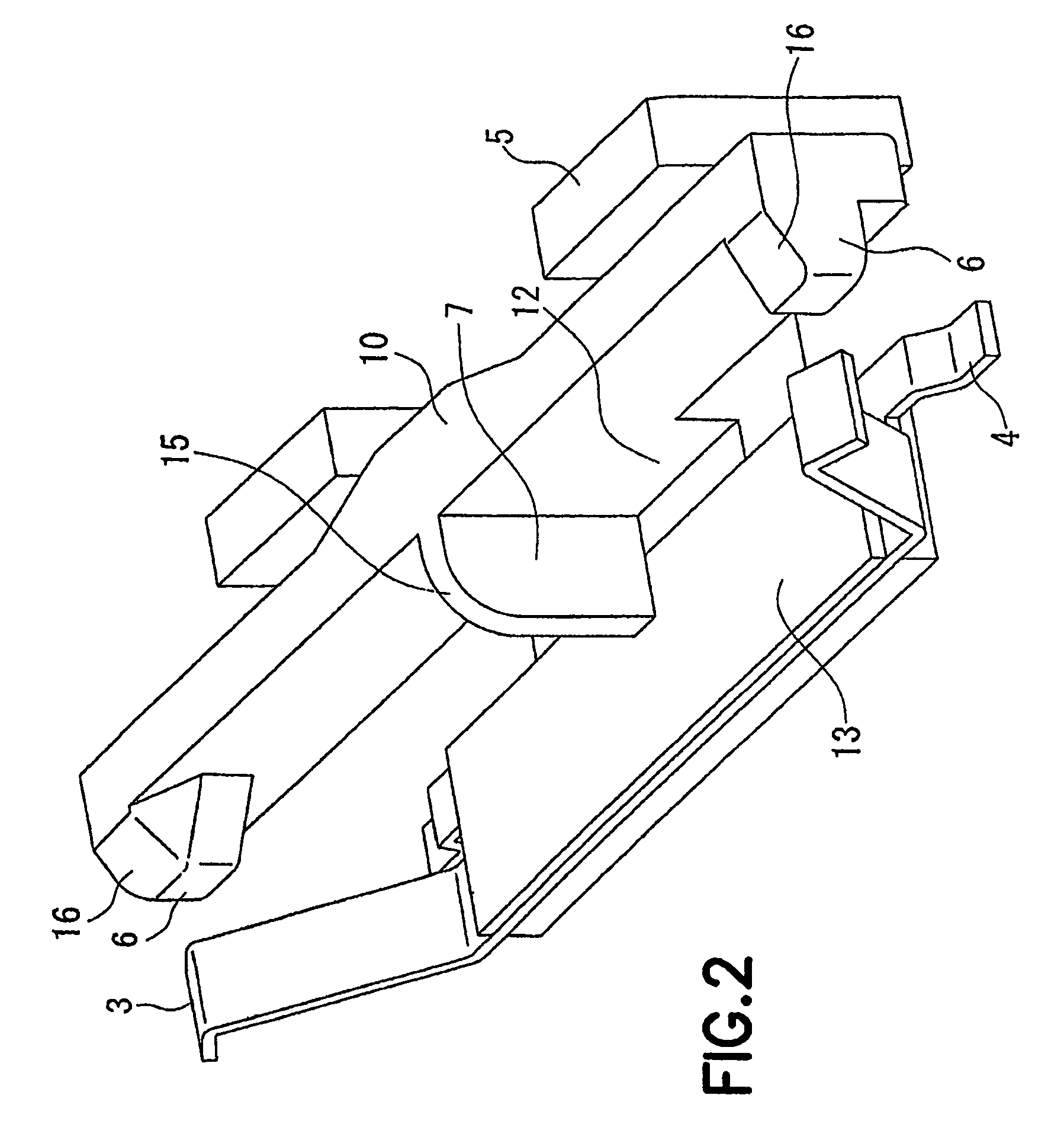
[0075]FIG. 2 shows a perspective view of an exemplary embodiment of the printed circuit board fixing device according to the present invention. Said board fixing device is fixed by fixing portions 4 to a motherboard 1 (see FIG. 1). A base portion 10 extends along the edge to be fixed of a printed circuit board 2, and on both end portions of said base portion 10, when the printed circuit board 2 is fixed, protruding portions 6 covering por...

embodiment 2

[0082]FIGS. 5(a) and (b), similarly to FIG. 1, are external views showing the procedure of completely fixing a printed circuit board 2 to a single socket fixed motherboard 1 whereon a printed circuit board fixing device according to a separate embodiment of the present invention has been placed. In FIG. 5, said printed circuit board fixing device is integrally formed by molding in the form of the present embodiment, but this may be integrally formed by a metal member, and it is fixed by inserting a snap-type peg 21 (see FIG. 6) in the motherboard 1.

[0083]FIG. 6 shows a perspective view of the printed circuit board fixing device shown in FIG. 5. Base portions 20 joined to a mounting piece 23 extend via two supporting portions 24 along the edge of the printed circuit board 2 on the side to be fixed, and are inclined to some degree in the direction of the edge of the printed circuit board 2 in such a way that the edge of the printed circuit board 2 comes into contact with them in the v...

embodiment 3

[0089]FIG. 8, as explained in FIG. 1, is an external view showing, for a dual socket fixed-type motherboard 1 whereon a printed circuit board fixing device of a further separate embodiment according to the present invention is placed, on the one hand, the state immediately prior to the fixing operation of a printed circuit board 2, and on the other hand, the state where a printed circuit board 2 is already fixed.

[0090]FIG. 9 shows a perspective view of the printed circuit board fixing device shown in FIG. 8. Said circuit fixing device is formed from metallic material, and is shaped integrally by punching or the like. In said board fixing device, via two supporting portions 44 (see FIG. 10(a)) extending in a perpendicular direction from a back portion 40 extending in the direction of the edge of the side to be fixed of a printed circuit board 2, a surface of said back portion 40 and a surface of two base portions 30 extending along an extending direction are positioned opposite to ea...


PUM


Abstract

The present invention provides a board fixing device not having an arm portion along a side edge of a printed circuit board. In a connector having spring contacts forming a contact point row in a direction perpendicular to the insertion direction of a board, when one end of said board is rotated in a direction whereby the spring contacts are pressed while being put into contact with the said spring contacts, during the insertion of the printed circuit board into said connector, and the other end of the opposing printed circuit board is made to approach said board fixing device, a printed circuit board having a corresponding notched portion on its edge portion engages a stabilizing piece formed in a perpendicular direction from one surface of the base portion, and at the same time, engages a protruding portion protruding from said base portion, and is fixed against the driving force of the said spring contacts. Whereby, shaking or swinging in the horizontal direction relative to the motherboard are restricted due to the protruding piece, and shaking and swinging in the vertical direction relative to the motherboard are restricted due to the engaging of the protruding portion of the said base portion and the said other end portion of the printed circuit board.

Description

TECHNICAL AREA[0001]Concerns a board fixing device for fixing the other end of a printed circuit board, when one end of a printed circuit board for connecting having a contact portion, is inserted into a connector fixed to a motherboard.BACKGROUND ART[0002]Japanese Unexamined Patent Publication No. H08-185936 provides a socket for a printed circuit board having a housing with an insertion port for receiving a printed circuit board formed between a pair of opposing wall portions; a plurality of spring contacts with their respective contact points protruding from at least one wall portion to the interior of the insertion port, and forming a contact row along the longitudinal direction of the insertion port; a pair of latch arms extending from the portions in the vicinity of each end portion in the longitudinal direction of the insertion port of the abovementioned housing, and moving outwardly by being pressed by the side edge portions of this printed circuit board when the printed cir...

Claims


Application Information

Patent Timeline
Patent Type & Authority Patents(United States)
IPC IPC(8): H01R13/62H05K7/14
CPCH01R12/83H05K7/1417
Inventor KAMEDA, YASUTOSHI
Owner FRAMATOME CONNECTORS INT SA
Why Eureka
Try Eureka