System and method for analyzing a graphical program using debugging graphical programs

a graphical program and program technology, applied in the field of graphical programming, can solve the problems of complex task of programming a computer system to model or implement a process, user's programming skills and ability to interact with the computer system often become a limiting factor in the achievement of optimal utilization of the computer system, and user's inability to fully grasp techniques, etc., to achieve the effect of simple graphical programming techniques

Inactive Publication Date: 2007-11-27
NATIONAL INSTRUMENTS
View PDF11 Cites 106 Cited by
  • Summary
  • Abstract
  • Description
  • Claims
  • Application Information

AI Technical Summary

Benefits of technology

[0021]One embodiment of the present invention comprises a system and method for debugging and / or analyzing a main graphical program using one or more debugging graphical programs. Thus, the debugging tool can be created using simple high level graphical programming techniques, enabling the user to more easily create a custom debugging graphical program that can better serve the user's needs. The user can also utilize or modify a debugging graphical program supplied with the graphical programming development environment.
[0023]This association may be performed without modifying the main graphical program. Thus, a re-compilation of the main graphical program is not necessary. In other words, associating a debugging graphical program with a main graphical program does not modify or require recompilation of the main graphical program. This greatly simplifies the debugging process.
[0028]Thus, the present invention provides an improved system and method for debugging or analyzing a graphical program. The debugging graphical program can be created with simple graphical programming techniques. Further, the user can utilize a debugging graphical program without requiring modification and / or re-compilation of the graphical program being debugged or analyzed.

Problems solved by technology

When traditional text-based programming environments are used, the user's programming skills and ability to interact with the computer system often become a limiting factor in the achievement of optimal utilization of the computer system.
There are numerous subtle complexities which a user must master before he can efficiently program a computer system in a text-based environment.
The task of programming a computer system to model or implement a process often is further complicated by the fact that a sequence of mathematical formulas, steps or other procedures customarily used to conceptually model a process often does not closely correspond to the traditional text-based programming techniques used to program a computer system to model such a process.
Since a user often is not fully proficient in techniques for programming a computer system in a text-based environment to implement his solution, the efficiency with which the computer system can be utilized often is reduced.
Traditional users of these systems, however, often were not highly trained in programming techniques and, in addition, text-based programming languages were not sufficiently intuitive to allow users to use these languages without training.
Therefore, implementation of such systems frequently required the involvement of a programmer to write software for control and analysis of instrumentation or industrial automation data.
Thus, development and maintenance of the software elements in these systems often proved to be difficult.
Alternatively, the front panel may be used merely to view the input and output, or just the output, and the input may not be interactively manipulable by the user during program execution.
Because most computer programs and many programmed hardware devices contain thousands of lines of code, almost any new product is likely to contain “bugs”.
However, current debugging techniques for graphical programs are inadequate for some applications, and there is a need for more advanced debugging techniques and methods.
Prior art methods are limited in the amount of custom debugging and analysis functionality the user can create for his or her graphical program.

Method used


Image

  • System and method for analyzing a graphical program using debugging graphical programs
  • System and method for analyzing a graphical program using debugging graphical programs
  • System and method for analyzing a graphical program using debugging graphical programs

Examples


Embodiment Construction

Incorporation by Reference

[0043]The following references are hereby incorporated by reference in their entirety as though fully and completely set forth herein:

[0044]U.S. Pat. No. 4,914,568 titled “Graphical System for Modeling a Process and Associated Method,” issued on Apr. 3, 1990.

[0045]U.S. Pat. No. 5,481,741 titled “Method and Apparatus for Providing Attribute Nodes in a Graphical Data Flow Environment”.

[0046]U.S. Pat. No. 5,652,909 titled “Method and Apparatus for Providing Autoprobe Features in a Graphical Data Flow Diagram”.

[0047]The LabVIEW and BridgeVIEW graphical programming manuals, including the “G Programming Reference Manual”, available from National Instruments Corporation, are also hereby incorporated by reference in their entirety.

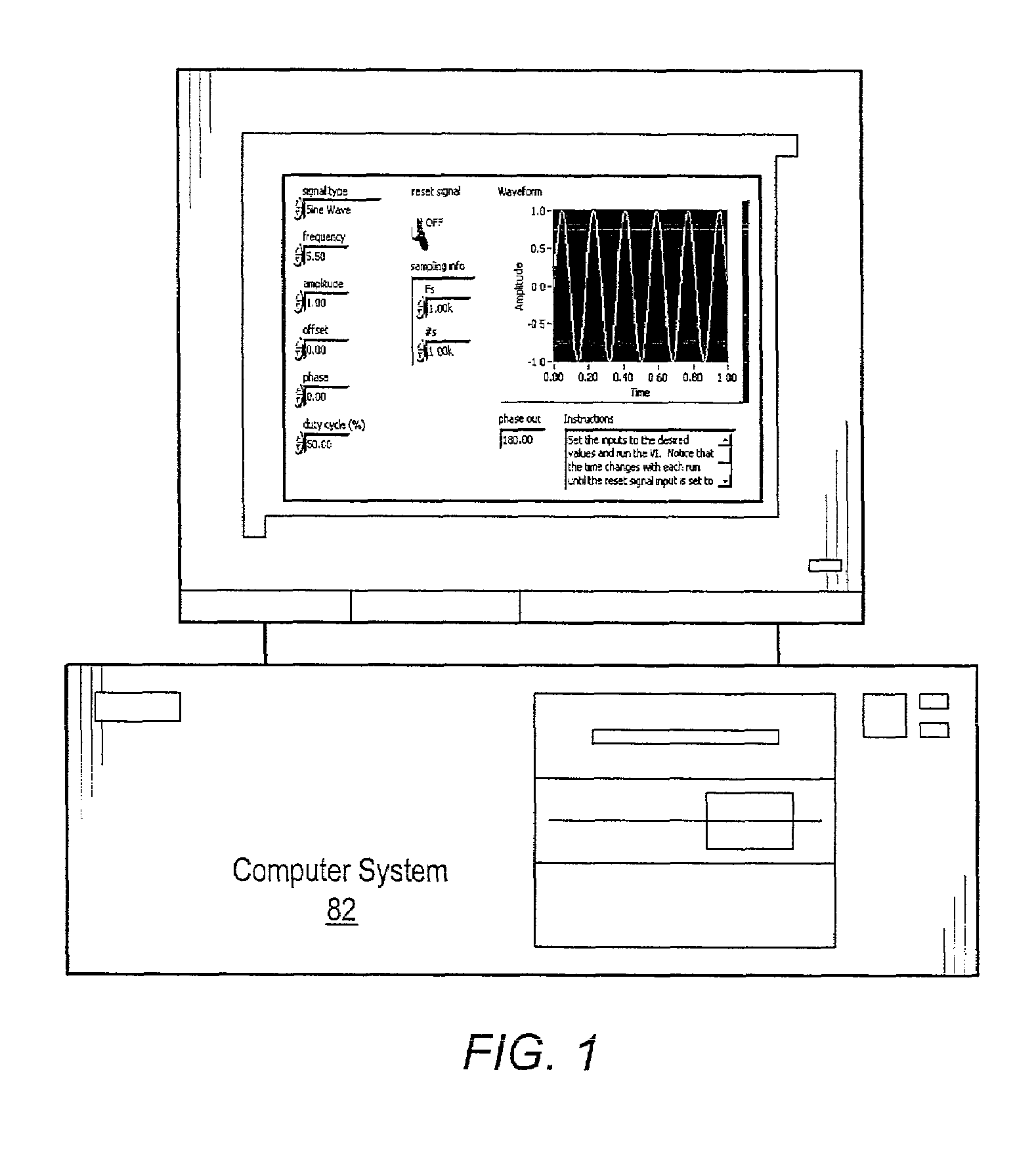
FIG. 1—Computer System

[0048]FIG. 1 illustrates a computer system 82 operable to create and / or execute a graphical program. The computer system 82 may be configured to implement various embodiments of the present invention. One embodiment ...


PUM


Abstract

A system and method for implementing a debugging graphical program in a main graphical program. A user can associate a debugging graphical program with a wire in a data flow diagram in order to debug and / or analyze the main graphical program. This association does not change or require recompilation of the main graphical program. The debugging graphical program, or smart probe, receives the data from the main graphical program, analyzes this data, and can perform one of several actions. The debugging graphical program can display the data in the wire, generate statistics based on received data, log statistics or data to a file, or perform other analysis functions. The debugging graphical program can also cause the main graphical program into halting execution, entering single stepping mode, etc. The user may choose a debugging graphical program already present, or create one using graphical programming techniques.

Description

PRIORITY DATA[0001]This application claims benefit of priority of provisional application Ser. No. 60 / 312,259 titled “System and Method for Analyzing a Graphical Program Using Debugging Graphical Programs” filed on Aug. 14, 2001, whose inventors are Steven W. Rogers and Jeffrey L. Kodosky.FIELD OF THE INVENTION [0002]The present invention relates to the field of graphical programming, and more particularly to a system and method for enabling a graphical program to use and implement debugging graphical programs.DESCRIPTION OF THE RELATED ART[0003]Traditionally, high-level text-based programming languages have been used by programmers in writing application programs. Many different high-level programming languages exist, including Visual BASIC, C / C++, Java, FORTRAN, Pascal, COBOL, ADA, APL, etc. Programs written in these high level languages are translated to the machine language level by translators known as compilers or interpreters. The high level programming languages in this leve...

Claims


Application Information

Patent Timeline
Patent Type & Authority Patents(United States)
IPC IPC(8): G06F9/44G06F11/36
CPCG06F11/3664G06F8/34
Inventor ROGERS, STEVEN W.KODOSKY, JEFFREY L.
Owner NATIONAL INSTRUMENTS
Why Eureka
Try Eureka