

Patient interface for respiratory apparatus
a patient interface and respiratory apparatus technology, applied in mechanical apparatus, respirator, operating means/releasing devices, etc., can solve the problems of impaired patient freedom of movement, increased discomfort of patient, and inconvenient arrangement and tubing siz
Inactive Publication Date: 2007-12-04
RESMED LTD
View PDF263 Cites 160 Cited by
- Summary
- Abstract
- Description
- Claims
- Application Information
AI Technical Summary
Benefits of technology
[0009]Both of these commercially available devices use the standard large bore 20 mm inlet tubing which is substantially unrestricted downstream of the pump outlet and will not operate satisfactorily with pressure drop inducing components such as small bore tubing. This is thought (as will be apparent from the experimental data given hereafter) to be due to the large pressure drop which causes large pressure swings in the nose mask as the patient inspires and expires. In particular, because these prior art devices do not attempt to der
Problems solved by technology
In particular, the discomfort experienced by the patient also increases in proportion to the increase in mask pressure during breathing out.
However, this arrangement and tubing size are not particularly convenient as far as the comfort of the patient and control of the treatment are concerned.
In practice, patients wearing nose masks or equivalent devices including such tubing can turn only from side to side and the freedom of movement of the patient is impaired by the tubing.
Both of these commercially available devices use the standa
Method used
View moreImage
Smart ImageViewing Examples

Examples
 PUM
 Abstract
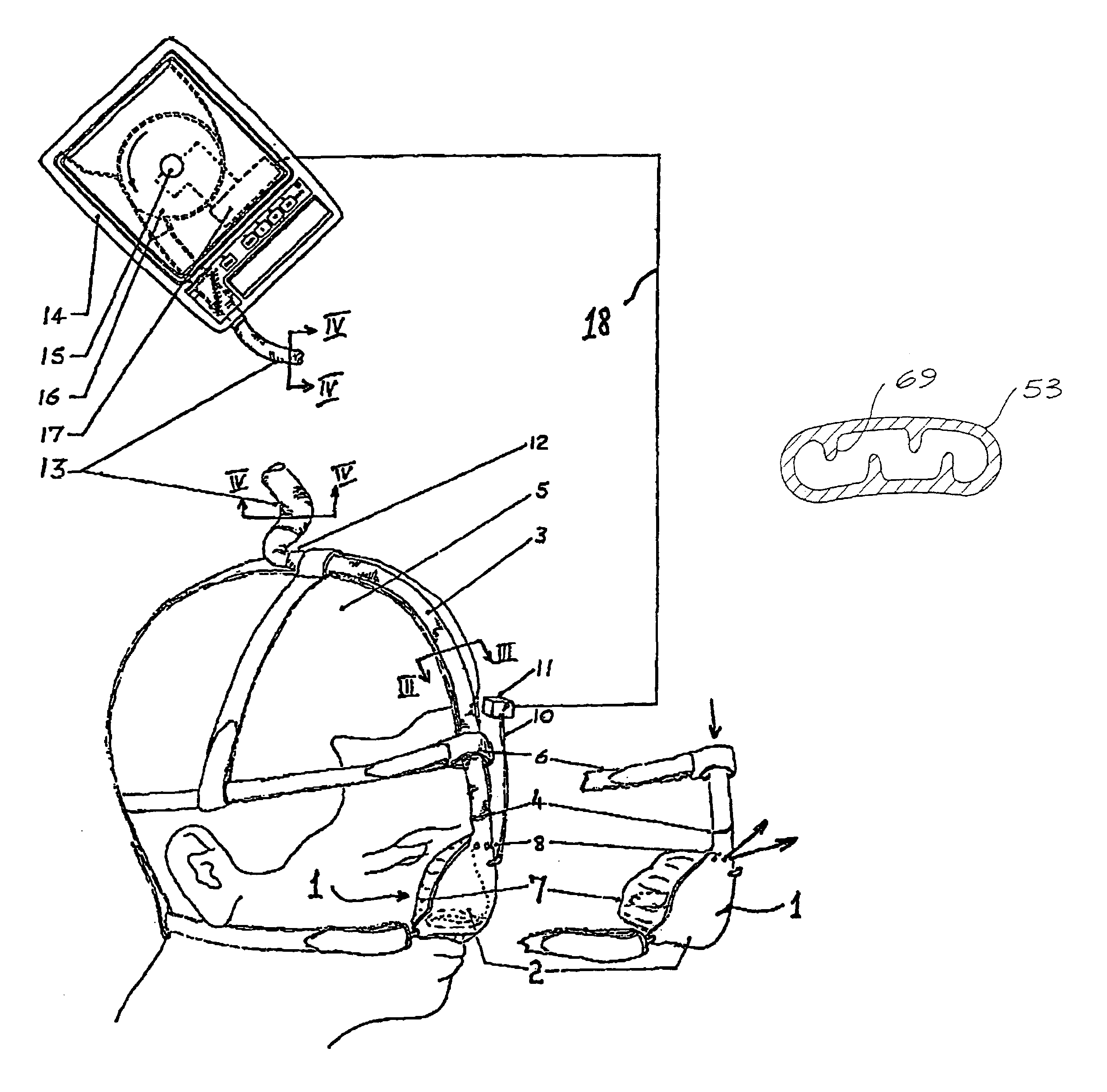
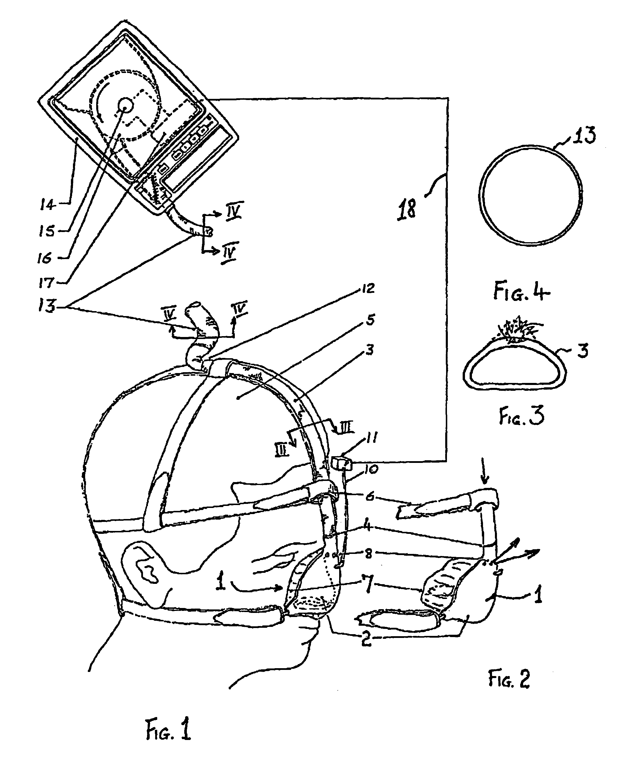
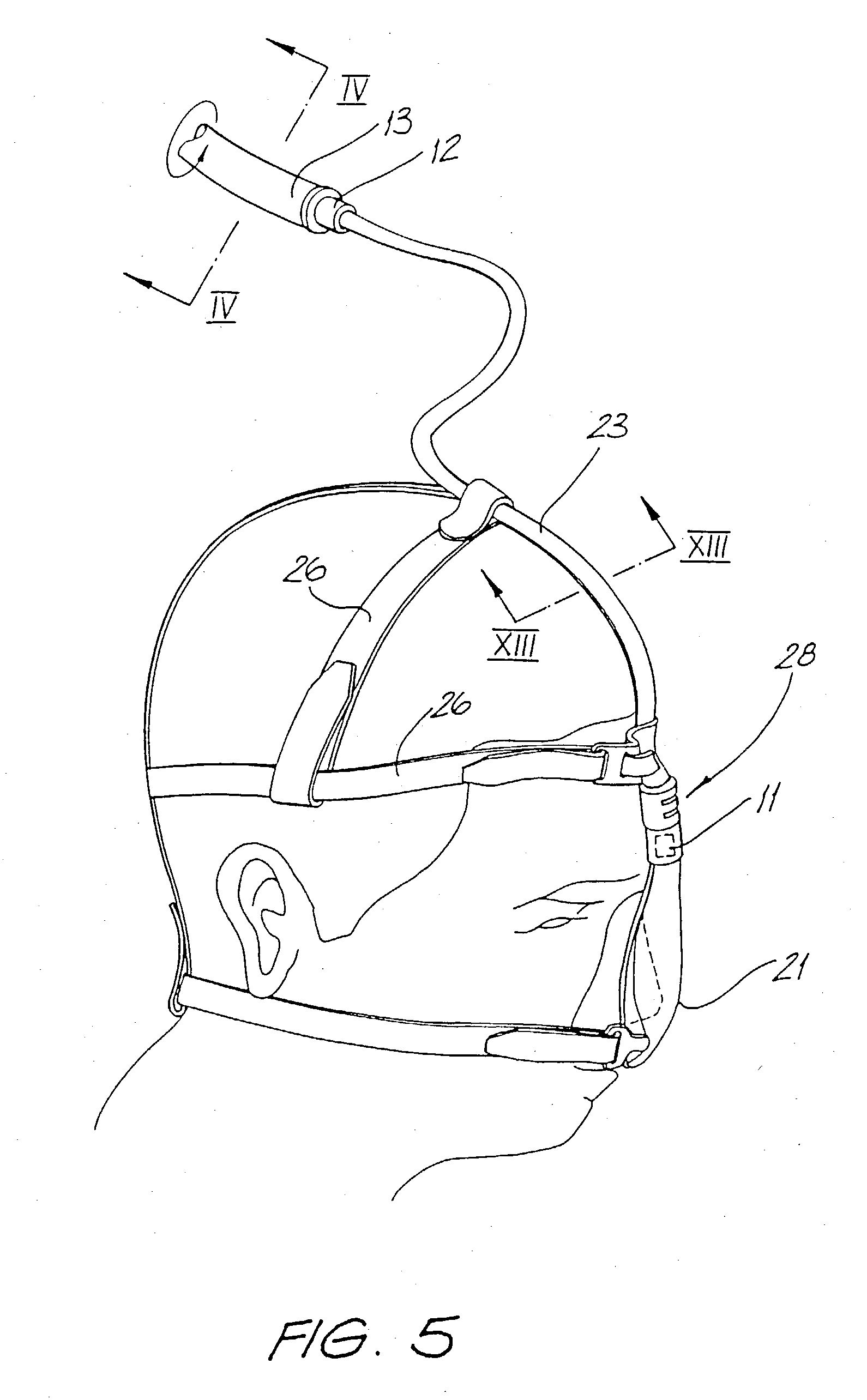
A patient interface assembly adapted to be connected to a gas supply pump to deliver breathable gas to the inlet of a patient's respiratory system comprises a supply conduit, a patient interface, a branch swivel connector including a Y-piece and an elbow that swivels relative to the Y-piece, the branch swivel connector being adapted to be located to the rear of a patient's head in use and being connected to the supply conduit. A pair of inlet tubes each have a first end positioned in use near a mouth of a patient and are connected to the nose mask, a middle portion arranged to pass across a cheek of a patient and an end portion being joined to the Y-piece of the branch connector. The inlet tubes have a flat configuration and are provided with a plurality of internal ribs which prevent the tubes being crushed. A strap is secured to the patient interface and adapted to pass around the sides and rear of the head to hold the patient interface in position on the head.
Description
CROSS REFERENCE TO RELATED APPLICATIONS[0001]This application is a Divisional Application of U.S. application Ser. No. 08 / 524,148, filed Sep. 6, 1995, now abandoned, which is a Continuation of U.S. application Ser. No. 07 / 994,153, filed Dec. 21, 1992, now abandoned, the specifications and drawings of which are incorporated herein by reference.BACKGROUND OF THE INVENTION[0002]The present invention relates to an improved CPAP respiratory apparatus which will increase patient comfort and therefore compliance.[0003]The fundamental disclosure of CPAP is made in the specification of PCT / AU82 / 00063 published under WO 82 / 03548 which discloses the supply of air to the nose of the patient at an elevated pressure, the air being supplied through a large bore inlet tube. The elevated pressure at which the air is supplied is approximately 10 cm water gauge although pressures in the range of approximately 5–20 cm water gauge are encountered. However, this pressure is measured while the patient is ...
Claims
Login to View More Application Information
Patent Timeline
 IPC IPC(8): A61M16/00A62B18/02F16L11/00A61M16/06A61M16/08
CPCA61M16/00A61M16/06A61M16/0683A61M16/0677A61M16/0069A61M16/0616A61M16/0633A61M16/08A61M16/1045A61M2210/0618A61M2016/0039A61M16/0825A61M16/0833A61M16/0858A61M16/022
InventorBERTHON-JONES, MICHAELCALLUAUD, MICHELLYNCH, CHRISTOPHER EDWARDSULLIVAN, COLIN EDWARD
OwnerRESMED LTD