Ceramic container and battery and electric double layer capacitor using the same

a ceramic container and double layer capacitor technology, applied in the direction of cell components, cell components, jackets/cases materials, etc., can solve the problems of deteriorating the electrolyte b-b>4/b, degrading the performance of the battery or the electric double layer capacitor, etc., to achieve the effect of improving airtight reliability and hardening of the property

Active Publication Date: 2007-12-04
KYOCERA CORP
View PDF9 Cites 58 Cited by
  • Summary
  • Abstract
  • Description
  • Claims
  • Application Information

AI Technical Summary

Benefits of technology

[0012]Hence, the invention has been made in consideration of the problems and its object is to provide a ceramic container which does not generate a drawback that a component of a first metallized layer of the ceramic container is eluted into an electrolyte due to corrosion of the metallized layer caused by the electrolyte, resulting in a damage of the performance of a battery or electric double layer capacitor using the ceramic container, a great deterioration in an electrical conductivity of the first metallized layer due to the corrosion and disconnection, and provide an battery and electric double layer capacitor having a high performance using the ceramic container.

Problems solved by technology

However, there is a problem in that the use of the electrolyte B-4 having a high performance causes a component of the first metallized layer 12a to be dissolved into the electrolyte B-4, thereby deteriorating the electrolyte B-4 and degrading the performance of the battery or the electric double layer capacitor, or the corrosion of the first metallized layer 12a causes an electrical conductivity of the first metallized layer 12a to be damaged, and furthermore, the first metallized layer 12a to be disconnected.

Method used


Image

  • Ceramic container and battery and electric double layer capacitor using the same
  • Ceramic container and battery and electric double layer capacitor using the same
  • Ceramic container and battery and electric double layer capacitor using the same

Examples


Embodiment Construction

[0059]Now referring to the drawings, preferred embodiments of the invention are described below.

[0060]A ceramic container and a battery or an electric double layer capacitor using the ceramic container according to the invention will be described below in detail.

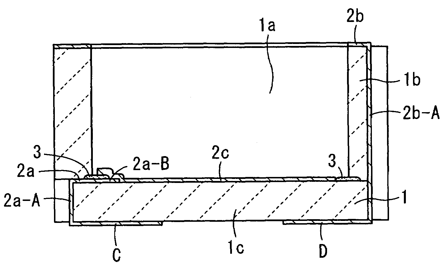
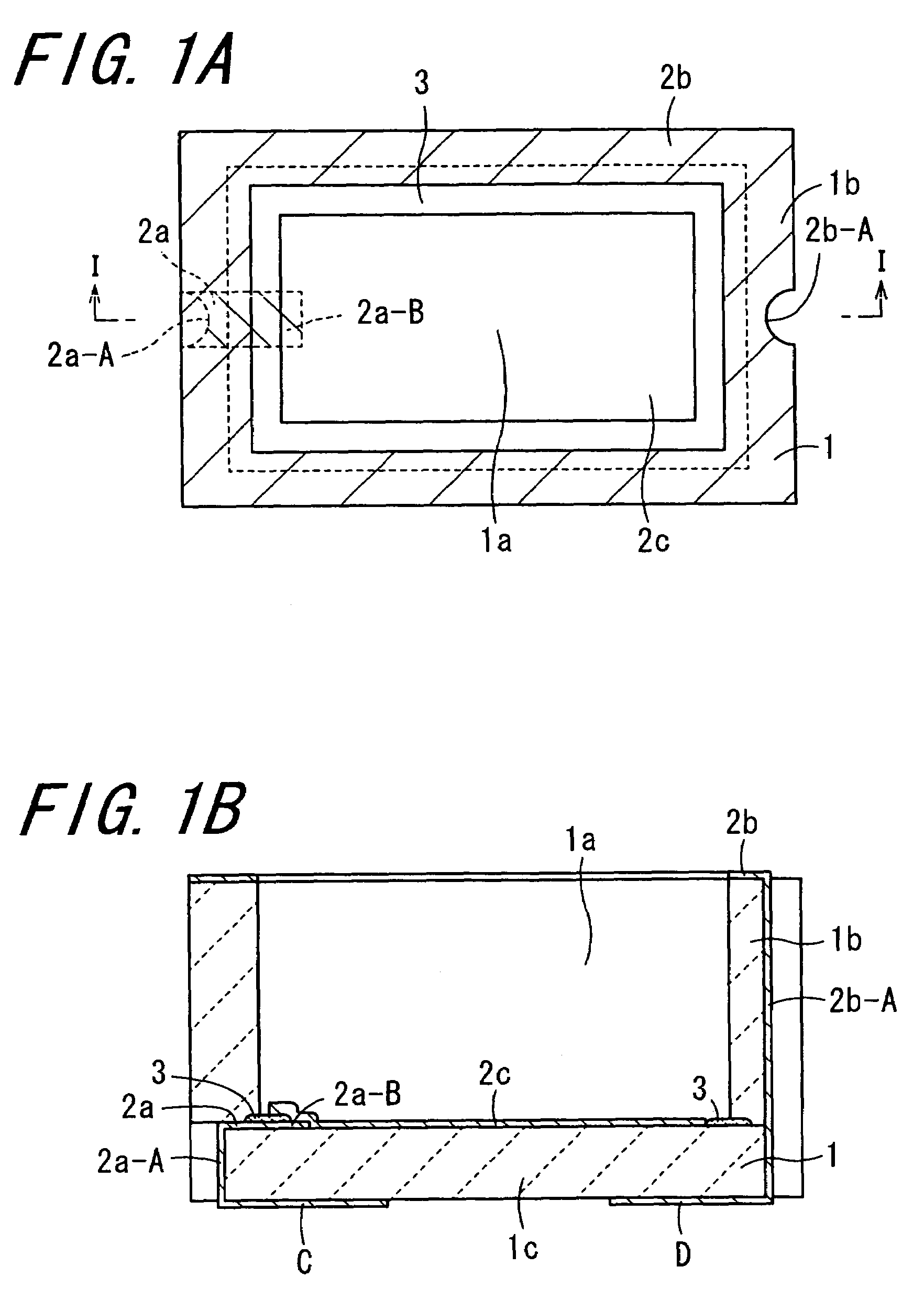
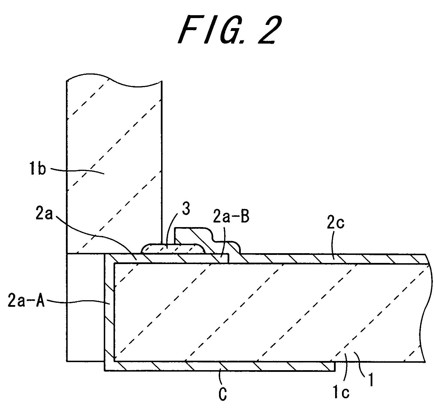
[0061]FIG. 1A is a plan view showing one embodiment of a ceramic container according to the invention, and FIG. 1B is a sectional view taken on line I-I of FIG. 1A. Moreover, FIG. 2 is an enlarged sectional view showing a main part (a left and lower portion) in FIG. 1B. Furthermore, FIG. 3A is a plan view showing the ceramic container according to another embodiment of the invention and FIG. 3B is a sectional view taken on line II-II of FIG. 3A. In addition, FIG. 4 is an enlarged sectional view showing a main part (a left and lower portion) in FIG. 3B.

[0062]Referring to these drawings, the ceramic container includes a ceramic base 1, a metallized layer 2a, a ceramic coating layer 3 and a conductive layer 2c. The ceramic base...


PUM

PropertyMeasurementUnit
thicknessaaaaaaaaaa
temperatureaaaaaaaaaa
thicknessesaaaaaaaaaa

Abstract

A ceramic container includes a ceramic base having a hollow or open portion for accommodating a battery element or an electric double layer capacitor element, defined by a bottom portion and a side wall which surrounds a bottom surface of the bottom portion which bottom face faces the hollow or open portion, a ceramic coating layer formed on a periphery of the bottom face along an inner face of the side wall, a first metallized layer extending, on the bottom face, from a portion provided immediately under the side wall to an inside of an inner end of the ceramic coating layer via a portion provided immediately under the ceramic coating layer, and a conductive layer formed on the bottom face in order to cover an extended portion of the first metallized layer and the ceramic coating layer.

Description

BACKGROUND OF THE INVENTION[0001]1. Field of the Invention[0002]The present invention relates to a ceramic container for a rechargeable battery and an electric double layer capacitor, and a battery and electric double layer capacitor using the same, and more particularly to a battery and an electric double layer capacitor which are used as a slim-type battery for a small-sized electronic apparatus such as a cellular phone, a backup power supply for a semiconductor memory, a spare power source for a small-sized electronic apparatus and the like, and a ceramic container used therefor.[0003]2. Description of the Related Art[0004]In recent years, the rapid development of portable apparatuses typified by a cellular phone, a mobile computer, a videotape recorder with an integrated camera and so on, has increased the need for reduced size and weight. At the same time, the demand for an increase in battery power has been increased research on size and weight reductions while increasing the ...

Claims


Application Information

Patent Timeline
Patent Type & Authority Patents(United States)
IPC IPC(8): H01G9/00H01G2/10H01G9/08H01G11/00H01G11/22H01G11/24H01G11/34H01G11/40H01G11/44H01G11/66H01G11/74H01G11/78H01G11/82H01G11/84H01M50/117H01M50/119H01M50/128H01M50/133
CPCH01G9/155H01M2/0257H01M2/0277H01G9/10H01M2/0292H01M10/052Y02E60/13H01M2/0287Y02E60/10H01M50/124H01M50/1245H01G11/74H01G11/78H01G11/80H01G11/82H01M50/133H01M50/117H01M50/119H01M50/128A01C1/02A01C1/044A01C1/042
Inventor USHIO, YOSHIHIROYOKOI, KIYOTAKAMIYAISHI, MANABUYASUI, MASAKAZU
Owner KYOCERA CORP
Why Eureka
Try Eureka