Vehicle control apparatus and vehicle control method

a technology of vehicle control and control apparatus, which is applied in the direction of process and machine control, road transportation, instruments, etc., can solve the problems of excessive power storage amount, reduced fuel efficiency of the vehicle, and gradual decrease of power storage amount in the secondary battery, so as to reduce the reduction of power storage amount, increase the amount of power generated, and increase the effect of power generation amoun

Active Publication Date: 2016-05-05
TOYOTA JIDOSHA KK
View PDF6 Cites 1 Cited by
  • Summary
  • Abstract
  • Description
  • Claims
  • Application Information

AI Technical Summary

Benefits of technology

[0021]As described above, when the power storage amount decreases as the vehicle alternates repeatedly between the acceleration travel and the coasting travel even in a case where the power generation unit converts the engine output into electric power during the acceleration period, the power generation unit may suppress the reduction in the power storage amount by increasing the amount of power generated during the acceleration period. The power generation amount is typically increased by increasing the engine output. However, an increase in the engine output leads to variation in an operating point of the internal combustion engine, and when the operating point of the internal combustion engine is modified, the efficiency of the powertrain of the vehicle, the powertrain including the internal combustion engine, varies (deteriorates, for example). When the efficiency of the powertrain varies (deteriorates, for example), the fuel efficiency of the vehicle varies (deteriorates, for example). Therefore, when the amount of power generated during the acceleration period is increased in order to suppress deterioration of the fuel efficiency due to an excessive reduction in the power storage amount, the efficiency of the powertrain may deteriorate, causing the fuel efficiency to deteriorate even further.
[0022]According to the configuration described above, the second control unit controls the power generation unit to convert at least one of the engine output and the kinetic energy into electric power during the coasting period when the efficiency of the powertrain deteriorates by at least the predetermined amount after the amount of power generated during the acceleration period is increased so as to suppress a reduction in the power storage amount as the vehicle alternates repeatedly between the acceleration travel and the coasting travel. As a result, an excessive reduction in the length of the coasting period is suppressed while also favorably suppressing deterioration of the fuel efficiency of the vehicle due to an excessive reduction in the power storage amount of the power storage unit and deterioration of the fuel efficiency of the vehicle due to deterioration of the efficiency of the powertrain.

Problems solved by technology

Depending on travel conditions of the hybrid vehicle and so on, however, an amount of power stored in the secondary battery (a power storage amount) may decrease gradually when the motor simply converts the engine output into charging power during the acceleration travel.
When the power storage amount continues to decrease in this manner, the power storage amount may decrease excessively.
As a result, a fuel efficiency of the vehicle may deteriorate in accordance with the excessive reduction in the power storage amount.
When the acceleration coasting travel is terminated in the vehicle in a condition where the power storage amount has decreased excessively, for example, the reduced power storage amount means that the hybrid vehicle cannot travel using the output of the motor while the internal combustion engine is set in the inoperative condition.
As a result, the fuel efficiency may deteriorate correspondingly.
In a condition where the power storage amount has decreased excessively, however, it may be difficult to crank the internal combustion engine using the motor.
Accordingly, it may be difficult for the hybrid vehicle to continue the acceleration coasting travel.
As a result, the fuel efficiency may deteriorate correspondingly.

Method used


Image

  • Vehicle control apparatus and vehicle control method
  • Vehicle control apparatus and vehicle control method
  • Vehicle control apparatus and vehicle control method

Examples


Embodiment Construction

[0039]An embodiment of a vehicle control apparatus according to the invention will be described below with reference to the drawings. Note that in the following description, the vehicle control apparatus according to this embodiment of the invention is applied to a hybrid vehicle 10.

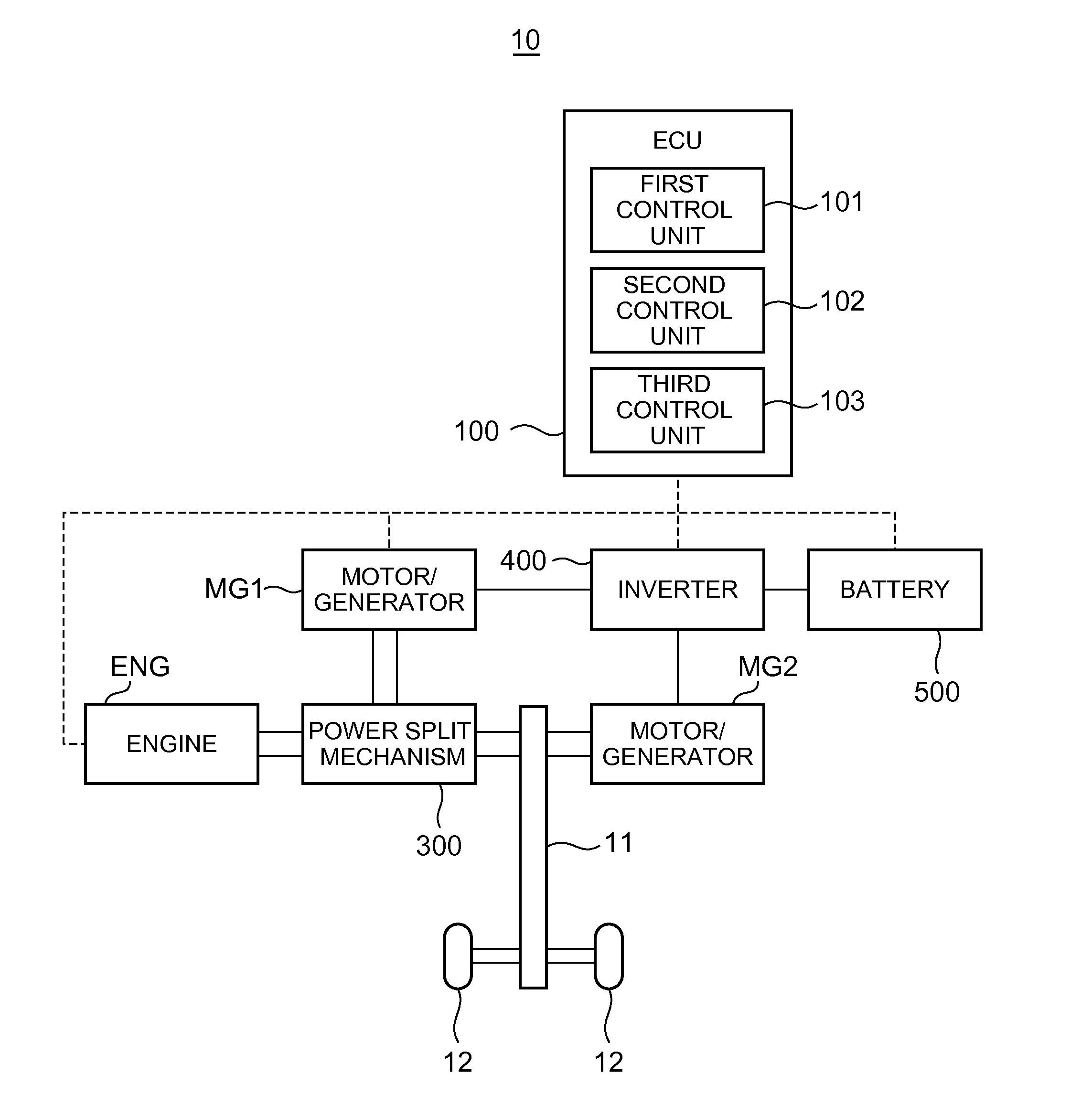
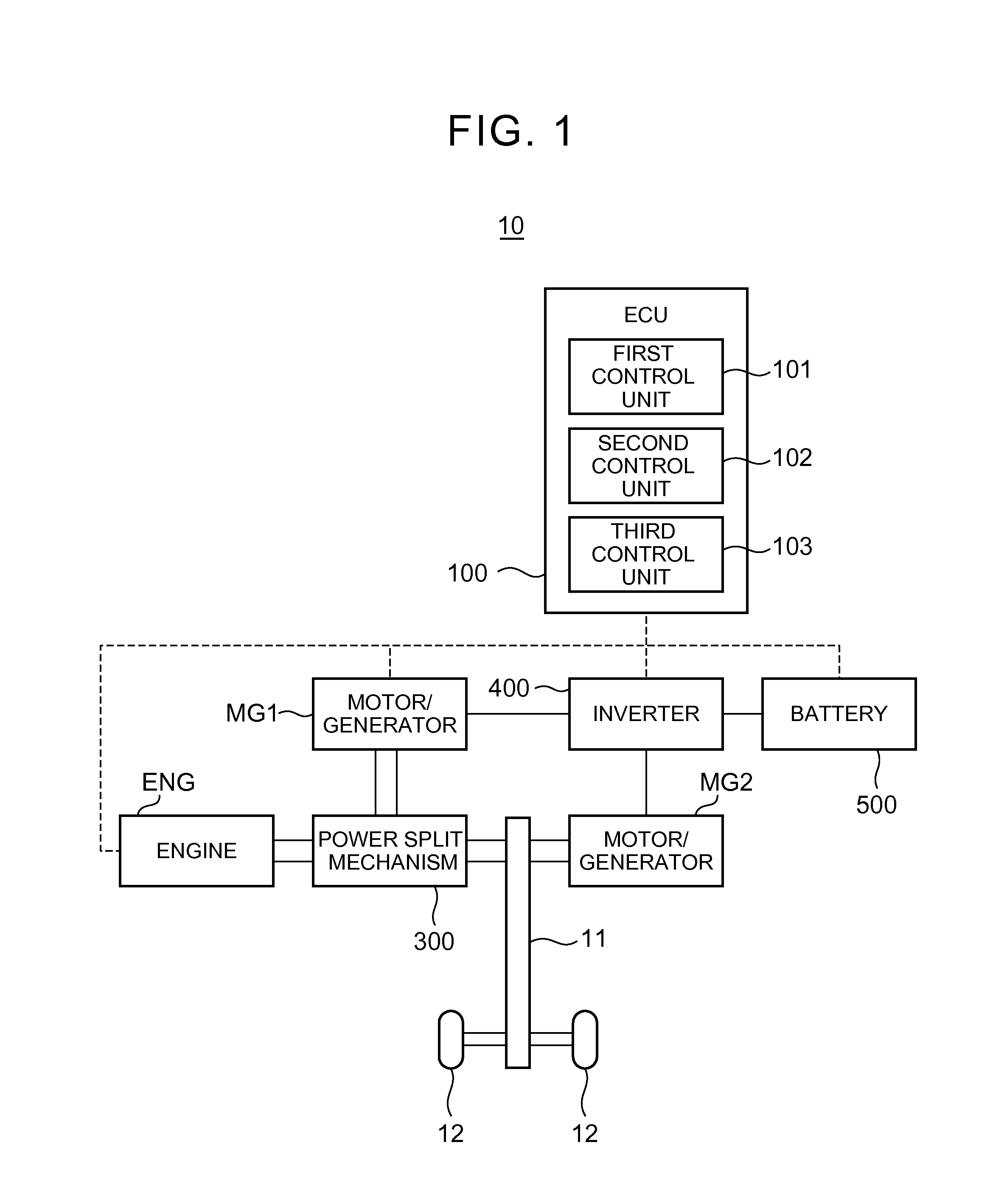
[0040]First, referring to FIG. 1, a configuration of the hybrid vehicle 10 according to this embodiment will be described. Here, FIG. 1 is a block diagram showing an example of the configuration of the hybrid vehicle 10 according to this embodiment.

[0041]As shown in FIG. 1, the hybrid vehicle 10 includes an axle 11, vehicle wheels 12, an electronic control unit (ECU) 100 serving as a specific example of a “vehicle control apparatus”, an engine ENG serving as a specific example of an “internal combustion engine”, a motor / generator MG1 serving as a specific example of a “power generation unit (power generating means)”, a motor / generator MG2 serving as a specific example of the “power generation unit (power...


PUM


Abstract

A vehicle control apparatus controls a vehicle including an internal combustion engine, a power generation unit that converts at least one of an engine output of the internal combustion engine and a kinetic energy of the vehicle into electric power, and a power storage unit that stores the electric power. The vehicle control apparatus includes: a first control unit configured to control the vehicle to alternate repeatedly between acceleration travel, in which the vehicle accelerates using the engine output, and coasting travel, in which the vehicle coasts without using the engine output, such that a vehicle speed is maintained within a predetermined speed region; and a second control unit configured to control the power generation unit to convert at least one of the engine output and the kinetic energy into electric power during a coasting period in which the vehicle performs the coasting travel.

Description

INCORPORATION BY REFERENCE[0001]The disclosure of Japanese Patent Application No. 2014-222356 filed on Oct. 31, 2014 and 2015-107713 filed on May 27, 2015, each including the specification, drawings and abstract, is incorporated herein by reference in its entirety.BACKGROUND OF THE INVENTION[0002]1. Field of the Invention[0003]The invention relates to a vehicle control apparatus and a vehicle control method for controlling a vehicle.[0004]2. Description of Related Art[0005]Japanese Patent Application Publication No. 2010-280363 (JP 2010-280363 A) describes a vehicle control apparatus that controls a vehicle having an internal combustion engine that can be switched between an operative condition and an inoperative condition to perform acceleration coasting travel. Here, the acceleration coasting travel as described in JP 2010-280363 A is travel performed in a set vehicle speed region by alternating repeatedly between acceleration travel and coasting travel. During the acceleration tr...

Claims


Application Information

Patent Timeline
Patent Type & Authority Applications(United States)
IPC IPC(8): B60W20/15B60W10/26B60W10/06B60W10/08B60W20/13B60W30/188B60L50/16
CPCB60W20/15B60W20/13B60W30/188B60W10/06B60W10/08B60W2720/106Y10S903/905Y10S903/906Y10S903/907Y10S903/93B60W2510/244B60W10/26B60L50/16B60W20/40B60K6/445B60W20/00B60W30/18072B60W2030/1809B60W30/143Y02T10/40Y02T10/62Y02T10/60
Inventor AMANO, TAKASHIAIKAWA, HIDEHUMI
Owner TOYOTA JIDOSHA KK
Why Eureka
Try Eureka