Liquid discharge apparatus and method for discharging liquid

a liquid discharge apparatus and liquid discharge technology, applied in the field of liquid discharge apparatus, can solve the problems of uneven streaks, inability to compensate, and different discharge characteristics of each liquid discharger, and achieve the effect of reducing the number of uneven streaks and improving printing quality

Inactive Publication Date: 2007-12-11
SONY CORP
View PDF13 Cites 46 Cited by
  • Summary
  • Abstract
  • Description
  • Claims
  • Application Information

AI Technical Summary

Benefits of technology

[0009]An object of the present invention is to compensate for the variation in the discharge characteristi...

Problems solved by technology

Therefore, for the line head, there is a problem in that the discharge characteristic of each liquid discharger varies greatly.
Thus, the line printer has a problem in that the characteristic of each l...

Method used


Image

  • Liquid discharge apparatus and method for discharging liquid
  • Liquid discharge apparatus and method for discharging liquid
  • Liquid discharge apparatus and method for discharging liquid

Examples


first embodiment

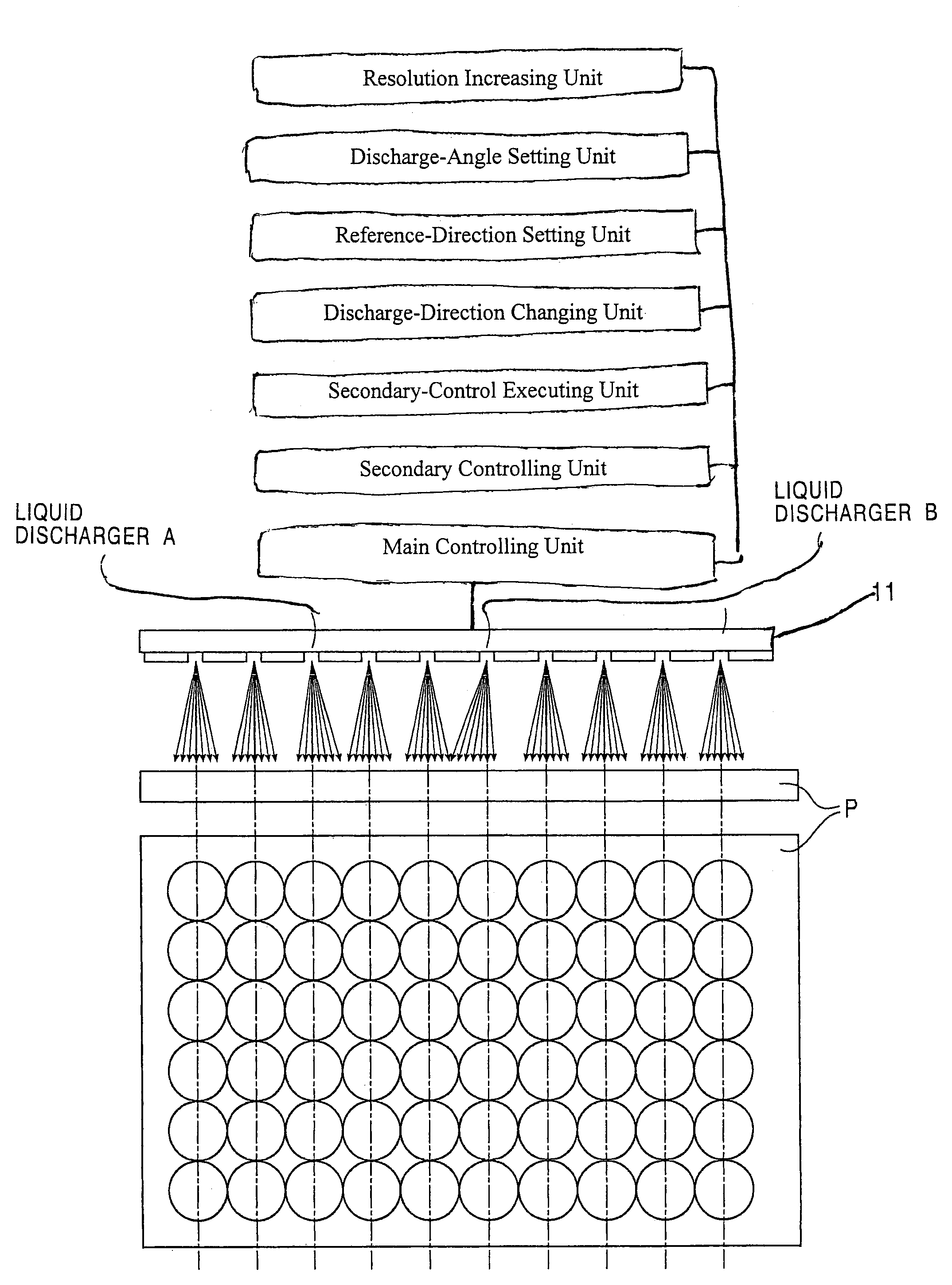
[0080]a head 11 according to the present invention includes a secondary-control executing unit in addition to the above-mentioned main controlling unit and secondary controlling unit.

[0081]The secondary-control executing unit determines whether or not a liquid discharger is going to operate the secondary controlling Unit.

[0082]FIG. 6 illustrates the landing position of ink droplets being compensated for by a main controlling unit, a secondary controlling unit, and a secondary-control executing unit. The upper portion of the drawing is a front view illustrating each liquid discharger of a head 11. The arrows indicate each trajectory of the ink droplets discharged from each liquid discharger using the main controlling unit and the secondary controlling unit. The bold arrows indicate the selected trajectories. The lower portion of the drawing is a plan view illustrating the ink droplets that have been discharged from each liquid discharger and landed on a recording medium. (The drawing...

second embodiment

[0091]a head 11 according to the present invention includes a reference-direction setting unit in addition to the above-mentioned discharge-direction changing unit.

[0092]The reference-direction setting unit selects one trajectory as the reference trajectory among the plurality of trajectories set by the discharge-direction changing unit for each liquid discharger.

[0093]Similar to the above, as illustrated in FIG. 6, the discharge-direction changing unit sets seven different trajectories of ink droplets for each liquid discharger.

[0094]At first, the reference-direction setting unit sets the trajectory in the middle of the seven trajectories as the reference trajectory.

[0095]Similar to the above, first, a test pattern is printed to detect whether or not there are any liquid dischargers having a discharge trajectory that is deflected more than the predetermined amplitude. Then, if a deflected liquid discharger is detected, the reference trajectory can be changed according to the deflec...

third embodiment

[0101]a head 11 according to the present invention includes a discharge-angle setting unit in addition to the above-mentioned discharge-direction changing unit.

[0102]The discharge-angle setting unit sets the angle of the trajectory of discharged ink droplets selected by the discharge-direction changing unit for each liquid discharger.

[0103]FIG. 7 illustrates an embodiment wherein the landing positions of ink droplets are compensated for by the discharge-direction changing unit and the discharge-angle setting unit.

[0104]Each liquid discharger is capable of discharging ink droplets along seven trajectories as described in the embodiment above. Moreover, each liquid discharger discharges ink droplets along the trajectory in the middle of the seven trajectories (the fourth trajectory from the left).

[0105]In this embodiment, as shown in FIG. 7, the liquid dischargers excepting liquid dischargers A and B discharge ink droplets along a trajectory substantially perpendicular to the surface ...


PUM


Abstract

A liquid discharge apparatus having heads with liquid dischargers including nozzles aligned in parallel in a row. Each liquid discharger has a main controlling unit for discharging ink droplets from the nozzles of the liquid discharger, a secondary controlling unit for controlling the discharge of a droplet so that the droplet is discharged along at least one trajectory different from the trajectories of the droplets discharged from a liquid discharger controlled by the main controlling unit, and a secondary-control executing unit for individually setting whether or not the secondary controlling unit for each liquid discharger is operated. The liquid dischargers controlled by the secondary controlling unit discharge ink droplets along different trajectories compared to the ink droplets discharged by other liquid dischargers.

Description

BACKGROUND OF THE INVENTION[0001]1. Field of the Invention[0002]The present invention is related to a liquid discharge apparatus including a plurality of heads having liquid dischargers with nozzles aligned in parallel in a row and a method for discharging liquid by using a plurality of heads having liquid dischargers with nozzles aligned in parallel in a row. More specifically, the invention relates to a technology for individually setting the trajectories of droplets for each liquid discharger and enabling each liquid discharger to discharge droplets in appropriate directions.[0003]2. Description of the Related Art[0004]One type of known liquid discharger is an inkjet printer. There are two types of known inkjet printers: 1) a serial printer in which a head is moved in the width direction of a recording medium while discharging droplets onto the recording medium as the recording medium moves in the feeding direction; 2) a line printer in which a line head is disposed across the wi...

Claims


Application Information

Patent Timeline
IPC IPC(8): B41J29/38B41J2/05B41J2/01B41J2/07B41J2/21
CPCB41J2/04505B41J2/04526B41J2/04533B41J2/04541B41J2/0458B41J2/04581B41J2/04595B41J2/2132B41J2/04578B41J2202/20B41J2/07
Inventor KUWAHARA, SOICHITAKENAKA, KAZUYASUUSHINOHAMA, IWAOIKEMOTO, YUICHIRO
Owner SONY CORP
Why Eureka
Try Eureka