Clamping nut for an osteosynthesis device

a technology of osteosynthesis and nut, which is applied in the direction of nuts, screws, dowels, etc., can solve the problems of inability to completely prevent the movement of the nut for screwing onto the threaded shank cannot be properly tightened, and the intervertebral connection element is subject to inappropriate stresses and cannot be completely prevented from moving

Active Publication Date: 2007-12-11
SCIENTX
View PDF16 Cites 95 Cited by
  • Summary
  • Abstract
  • Description
  • Claims
  • Application Information

AI Technical Summary

Benefits of technology

[0010]means for preventing relative turning between the ring and the annular body.

Problems solved by technology

Although an anchor screw of the type having a spherical joint makes it possible to achieve an adaptable relative angle between said screw and the intervertebral connection element, it must be considered that making a spherical joint on an anchor screw contributes to weakening it by including a moving interface that can even lead to the intervertebral connection element breaking.
Furthermore, it has been found that even in the presence of an anchor screw of the type having a spherical joint, the threaded shank does not always extend to project perpendicularly relative to the intervertebral connection element, given the anatomy of the vertebrae and the zone in which the anchor screw is implanted.
It follows that the nut for screwing onto the threaded shank can no longer be tightened properly, insofar as the intervertebral connection element does not extend perpendicularly to the threaded shank, such that the intervertebral connection element is subjected to inappropriate stresses and cannot be completely prevented from moving, at least not with appropriate clamping force.

Method used


Image

  • Clamping nut for an osteosynthesis device
  • Clamping nut for an osteosynthesis device
  • Clamping nut for an osteosynthesis device

Examples


Embodiment Construction

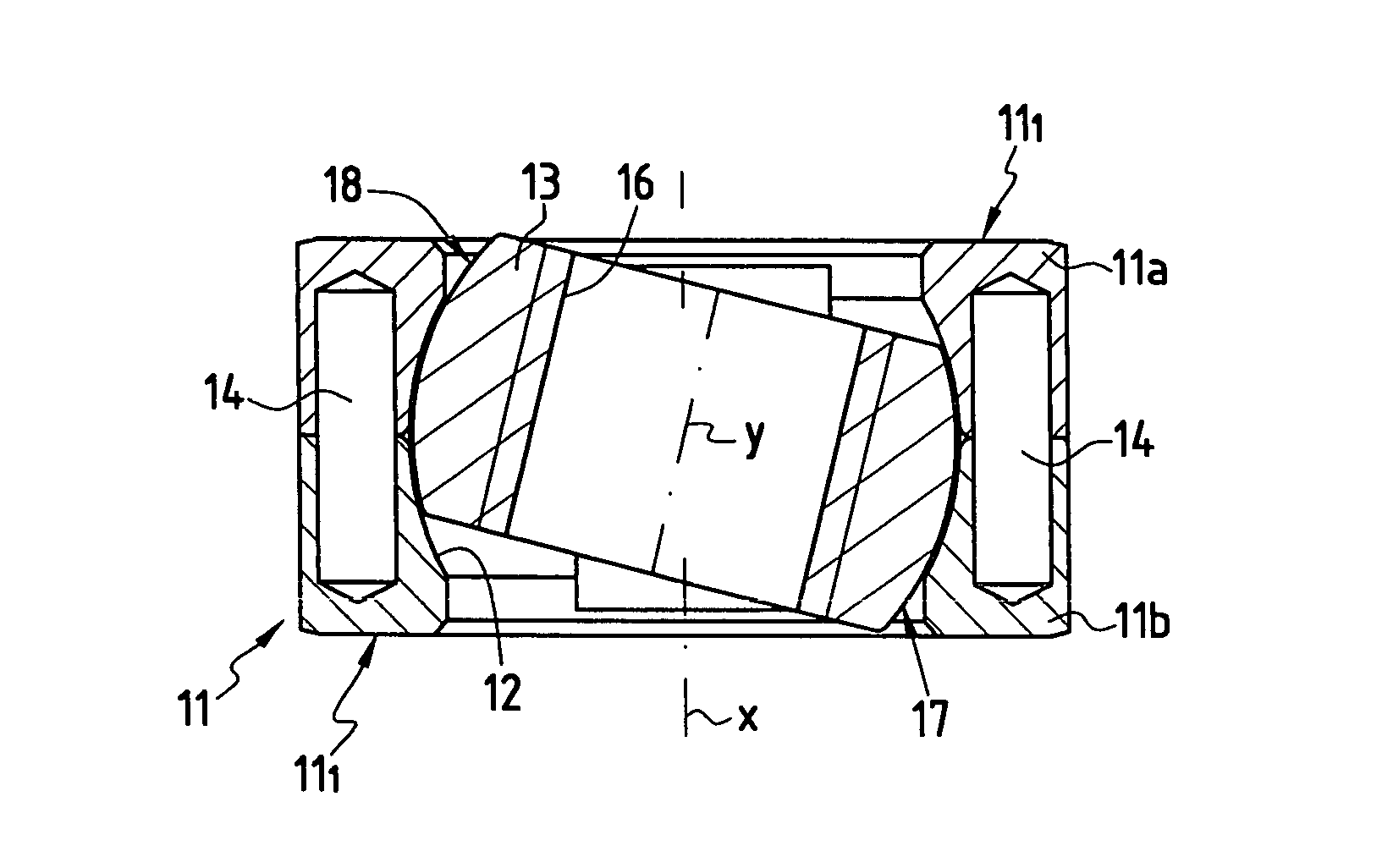
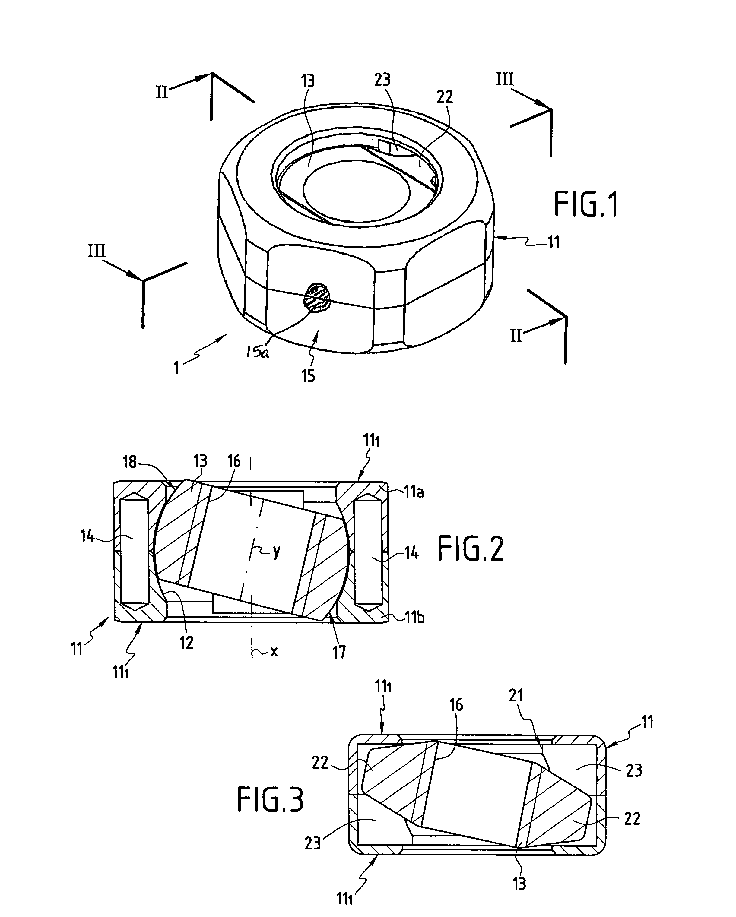
[0025]FIGS. 1 to 3 show a clamping nut 1 in accordance with the invention for use in an osteosynthesis device 2 for the spine.

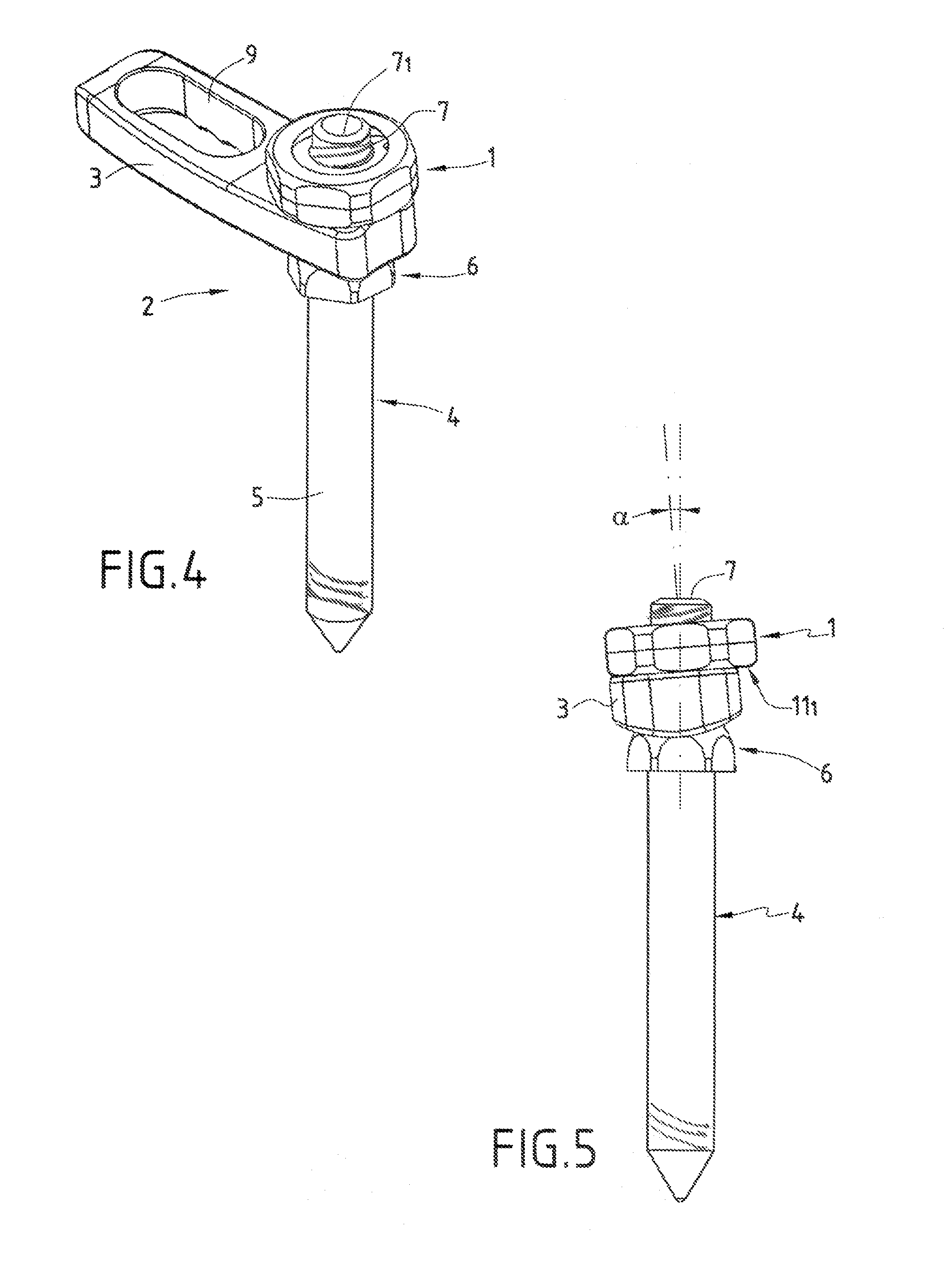
[0026]In the example shown in FIGS. 4 and 5, the osteosynthesis device 2 comprises an intervertebral connection element 3 such as a plate in the example shown together with at least one osteosynthesis appliance 4 in the general sense capable of being made in various known ways. The osteosynthesis appliance 4 thus constitutes, for example, a bone anchor element in the form of a hook or as shown in the drawings, in the form of an anchor screw. Such an osteosynthesis appliance 4 can also be in the form of a plate or of an intermediate connection element.

[0027]In the example shown, the osteosynthesis appliance 4 forming a bone anchor screw comprises a threaded portion 5 and a head 6 from which there extends a threaded shank 7. In the example shown, the threaded shank 7 extends substantially in line with the threaded portion 5. In known manner, the intervertebral ...


PUM


Abstract

A clamping nut suitable for co-operating with a threaded shank of an osteosynthesis appliance, the nut including an annular body and a tapped bore for cooperating with the threaded shank. The annular body is provided with a structure which enables turning the body and with a transverse bearing face. The osteosynthesis nut further includes a ring mounted in a housing of the annular body which is provided internally with the tapped bore, and which cooperates externally with the annular body.

Description

[0001]The present invention relates to the technical field of osteosynthesis, in particular of the spine, and it relates more particularly to a clamping nut used in osteosynthesis devices for the spine.[0002]More precisely, the invention provides a clamping nut designed to present an angle relative to an osteosynthesis appliance in the general sense.BACKGROUND OF THE INVENTION[0003]One of the known applications for the invention relates to devices designed to correct and hold a set of vertebrae in a determined position. In this application, such a device comprises an intervertebral connection element such as a plate or a rod suitable for being held in position by bone anchor elements such as screws implanted in the vertebrae. Each bone anchor element is provided with a head, and a threaded shank for mounting the plate which has through holes. The plate is engaged on the threaded shank via a through hole and the portion of the shank that projects from the plate is used for receiving ...

Claims


Application Information

Patent Timeline
Patent Type & Authority Patents(United States)
IPC IPC(8): A61B17/56A61B17/70A61B17/80A61B17/86
CPCA61B17/8033A61B17/7059A61B17/8665
Inventor CARLI, OLIVIER
Owner SCIENTX
Why Eureka
Try Eureka