Multi-axial bone screw mechanism

a multi-axial bone screw and mechanism technology, applied in the field of spinal surgery, can solve the problems of preventing the head from being pushed out of the coupling member, the coupling member must be able, and the coupling member is relatively large and bulky, so as to achieve the effect of sufficient bone screw size and strength, and a wide range of variable angular positions

Active Publication Date: 2007-12-11
ORTHOPAEDIC INT +1
View PDF19 Cites 268 Cited by
  • Summary
  • Abstract
  • Description
  • Claims
  • Application Information

AI Technical Summary

Problems solved by technology

One disadvantage of these systems is that since the threaded portion of the bone screw must go through the coupling member, the dimensions of the coupling member must be able to accommodate the largest thread diameter of the bone screw.
Typically, this results in a relatively large and bulky coupling member in a system that is desirably as small as possible.
However, one difficulty with bottom-loaded systems is preventing the head from being pushed out of the coupling member once it is inserted into the coupling member cavity.
However, this design is limited in the amount of angulation between the bone screw and the coupling member.
In order to increase the angulation, the neck diameter must be reduced, which could weaken the bone screw.

Method used


Image

  • Multi-axial bone screw mechanism
  • Multi-axial bone screw mechanism
  • Multi-axial bone screw mechanism

Examples


Embodiment Construction

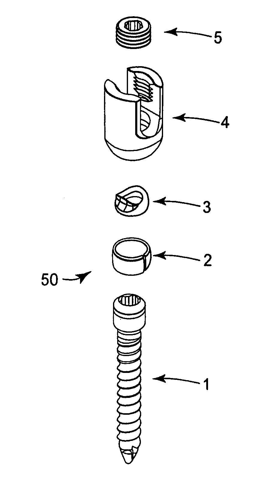
[0023]The present invention is related to a multi-axial bone screw assembly that can be securely attached to another component or member at a wide variety of different angles. In a particular preferred use, the bone screw assembly of the present invention is used primarily for spinal applications where a pedicle screw has to be securely attached to a spinal rod at varying angles, such as to provide a desired corrective spatial relationship between vertebral bodies. However, it is understood that the bone screw assembly of the present invention may instead be used for attachment to other components and / or in systems that are related to correction of other physical problems that may or may not be related to the spine.

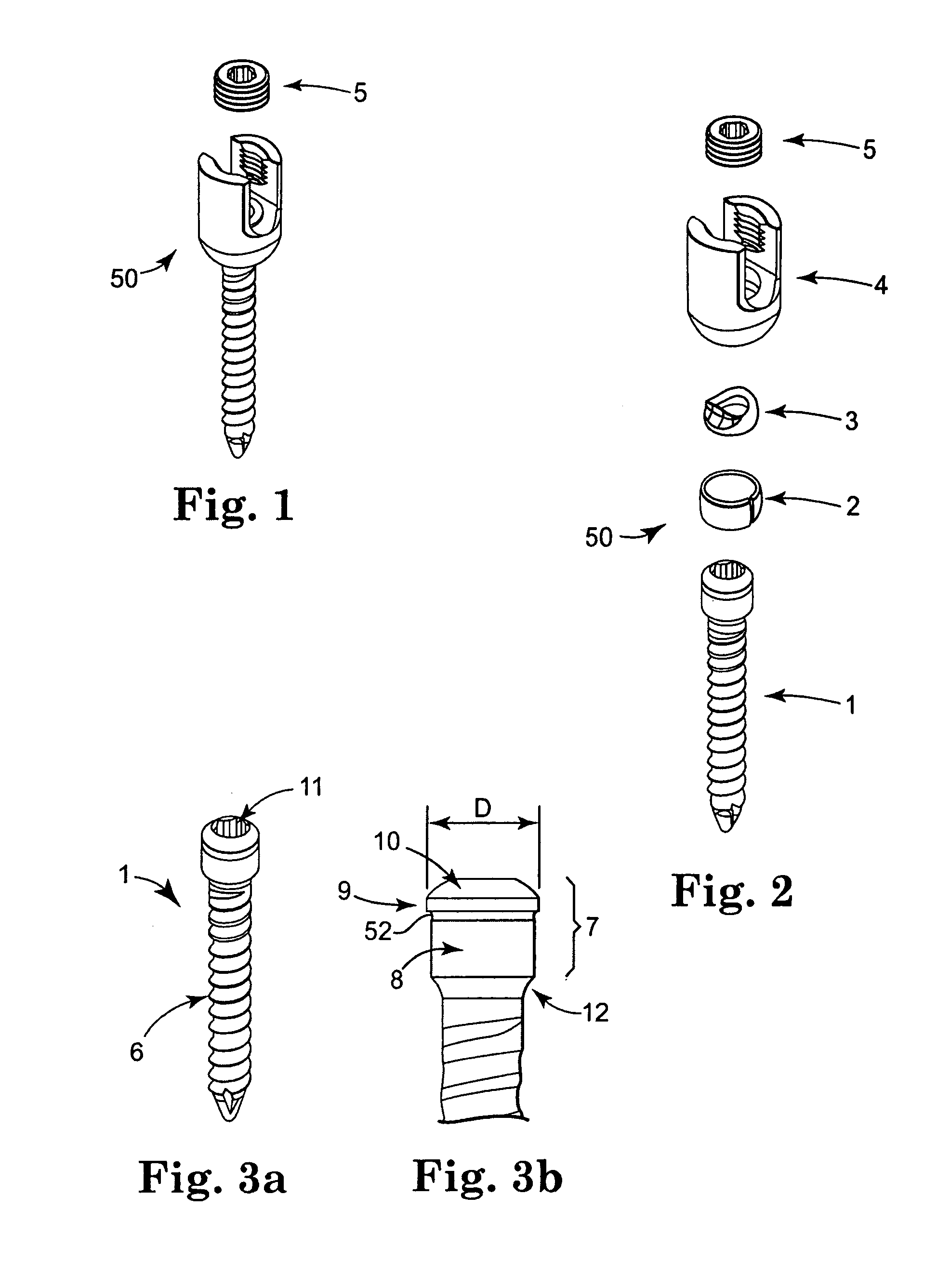
[0024]Referring now to the Figures, wherein the components are labeled with like numerals throughout the several Figures, and initially to FIGS. 1 and 2, one preferred configuration of a bone screw assembly 50 is illustrated, which generally includes a bone screw 1, a sph...


PUM


Abstract

A bone screw assembly including a coupling member with a lower surface and a channel formed by two arms extending from a base portion. The coupling member has a hole extending from the base portion of the channel to its lower surface. The assembly further includes a spacer having a top surface adjacent the base portion of the channel and a bottom surface generally opposite the top surface within the hole of the coupling member, and includes a hollow retaining ring within the hole of the coupling member, the retaining ring comprising an inner surface, an outer surface, a top surface spaced from the bottom surface of the spacer, and a slot extending from the inner surface of the ring to the outer surface of the ring. The assembly includes a bone screw having a head portion with an outer surface adjacent to the inner surface of the retaining ring.

Description

TECHNICAL FIELD[0001]The present invention relates generally to devices for use in spinal surgery and methods of using such devices. More particularly, the present invention relates to multi-axial bone screw mechanisms for anchoring a vertebral body to a spinal fixation system as part of a surgical procedure.BACKGROUND OF THE INVENTION[0002]Surgically implanted systems, such as fixation devices and apparatuses, are commonly used to correct a variety of back structure problems, including those that occur as a result of trauma or improper development during growth. Generally, these systems correct such problems by providing a desired corrective spatial relationship between vertebral bodies. A typical spinal fixation system generally comprises a support rod or system of support rods that are secured along at least a portion of the spinal column intended to be immobilized by bone screws or hooks or other bone engaging components. Particular systems may include one or more fixation rods ...

Claims


Application Information

Patent Timeline
Patent Type & Authority Patents(United States)
IPC IPC(8): A61B17/58
CPCA61B17/7037A61B17/7032
Inventor SASING, JUDE L.
Owner ORTHOPAEDIC INT
Why Eureka
Try Eureka