Fixing device having release agent applying unit and image forming apparatus

a technology of fixing device and release agent, which is applied in the direction of electrographic process apparatus, instruments, optics, etc., can solve the problems of degrading printing quality and inability to enable borderless printing, and achieve the effects of preventing the wounding of printing media, enhancing the repeatability of printing media from the fixing member, and eliminating blank margins

Inactive Publication Date: 2007-12-18
OKI DATA CORP
View PDF11 Cites 14 Cited by
  • Summary
  • Abstract
  • Description
  • Claims
  • Application Information

AI Technical Summary

Benefits of technology

[0004]An object of the present invention is to provide a fixing device and an image forming apparatus adaptable to borderless printing without causing the degradation of the printing quality.
[0006]With such an arrangement, the releasability of the printing medium from the fixing member can be enhanced, and therefore it becomes possible to prevent the printing medium from being wound around the fixing member. Thus, it becomes possible to eliminate the blank margin on the leading edge of the printing medium, and therefore it becomes possible to fix the borderless image.

Problems solved by technology

However, if the margin on the leading edge of the printing medium in the feeding direction of the printing medium is small, there is a possibility that the printing medium may not separate from the heat roller or the like and may be wound around the heat roller or the like.
Thus, a sufficient margin needs to be left on the leading edge of the printing medium, and therefore the borderless printing is not enabled.
However, in such a case, a large amount of release agent may adhere to the surface of the printing medium, with the result that the printing quality may be degraded.

Method used


Image

  • Fixing device having release agent applying unit and image forming apparatus
  • Fixing device having release agent applying unit and image forming apparatus
  • Fixing device having release agent applying unit and image forming apparatus

Examples


first embodiment

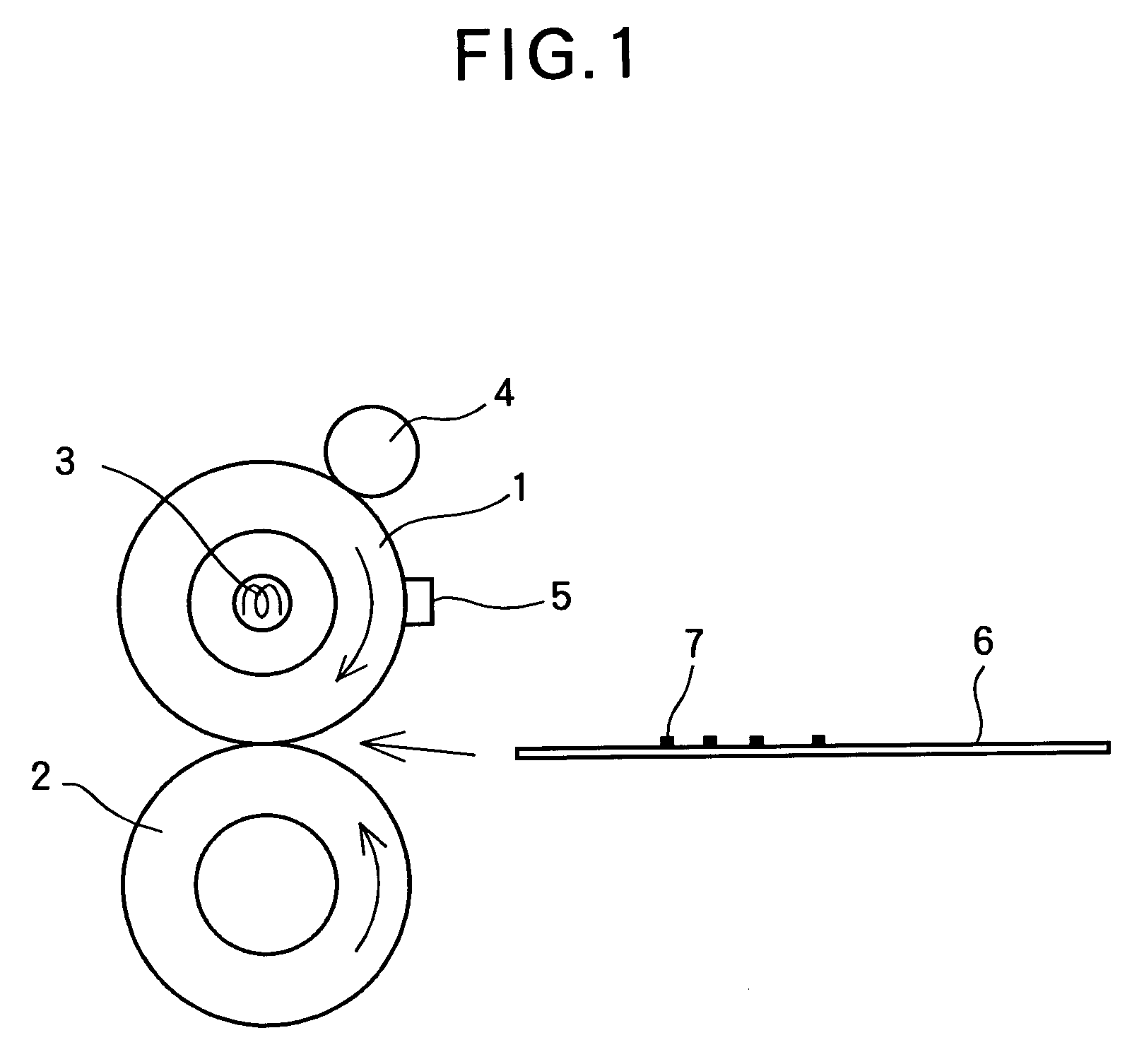
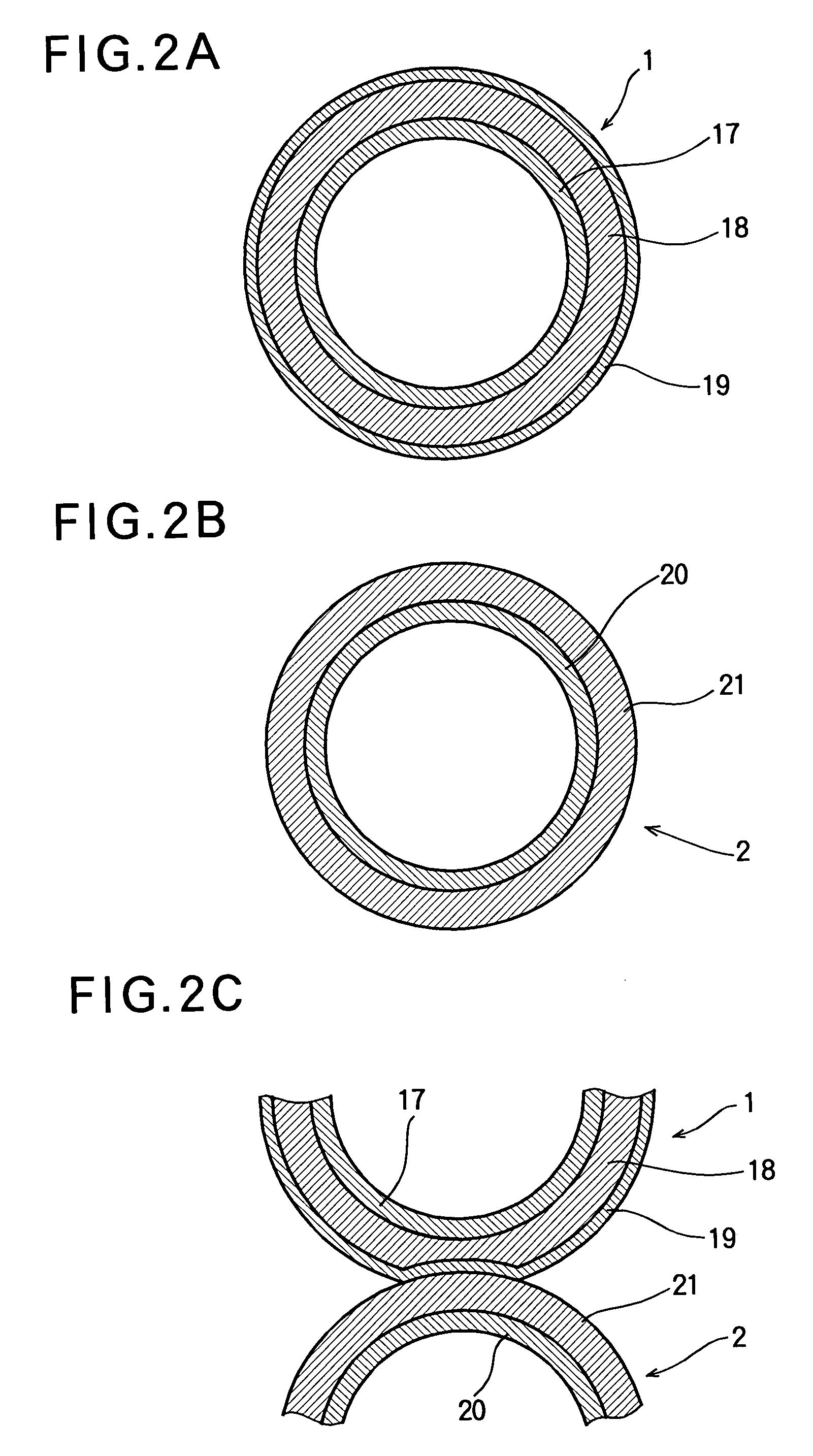
[0033]FIG. 1 shows the basic configuration of a fixing device according to the first embodiment of the present invention. The fixing device includes a fixing roller 1 and a pressure roller 2 disposed in parallel to each other. The fixing roller 1 is a so-called heat roller having an internal heat source 3. FIG. 2A is a sectional view showing the structure of the fixing roller 1, with the heat source 3 being omitted. The fixing roller 1 includes a core 17 in the form of a pipe, a resilient layer 18 formed on the core 17, and a release layer 19 covering the resilient layer 18. The core 17 is required to have a rigidity, and is made of a metal such as aluminum, iron, or stainless steel. The resilient layer 18 is made of rubber with excellent heat resistance such as general silicone rubber, sponge-like silicone rubber or fluoro-rubber. The release layer 19 is made of a material with excellent heat resistance and low surface free energy after the formation, such as a representative fluor...

second embodiment

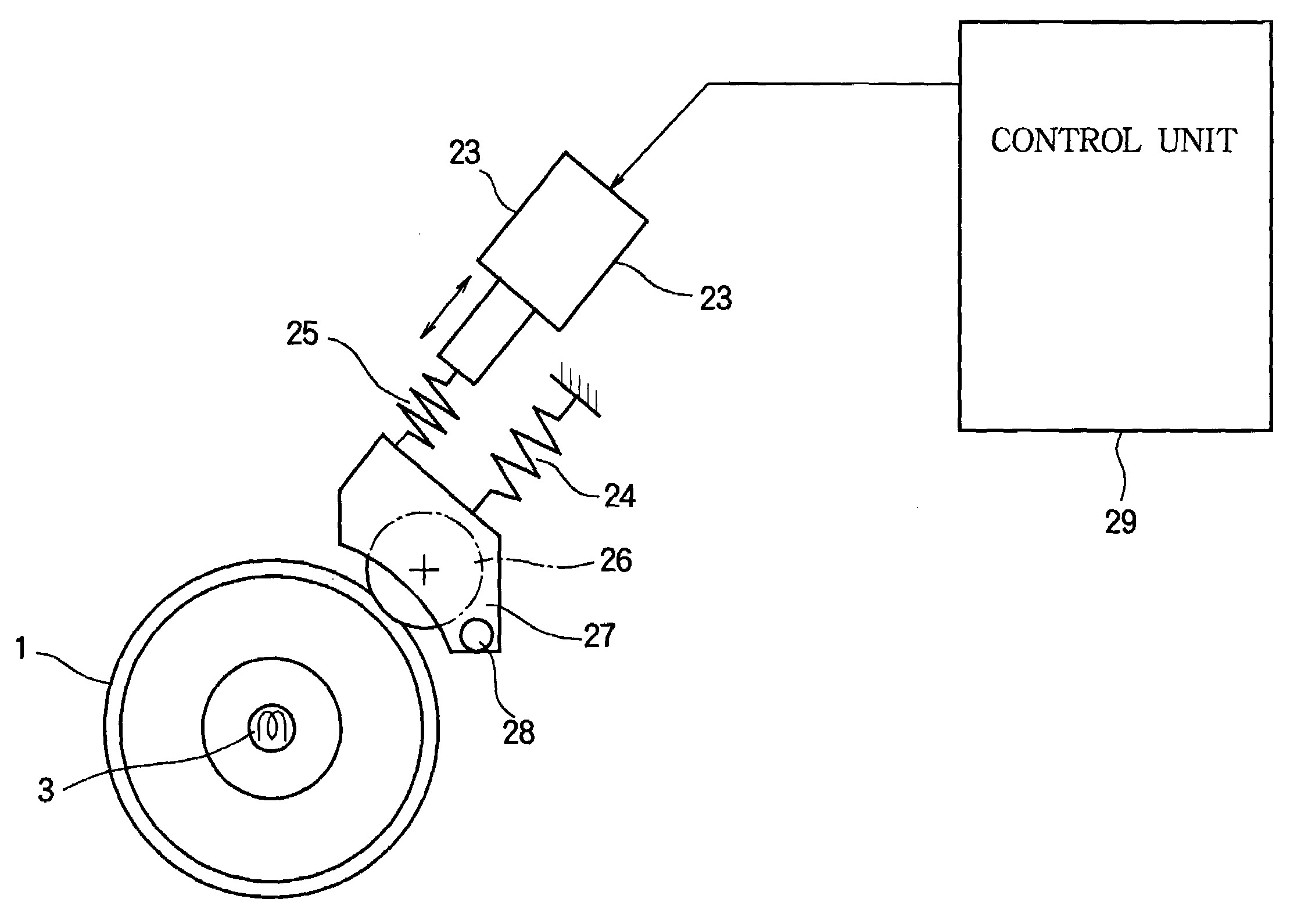
[0082]FIG. 8 shows the main part of a fixing device according to the second embodiment of the present invention. The fixing device has a contacting-and-separating mechanism that moves the release agent applying member 26 in contact with the fixing roller 1, and moves the release agent applying member 26 apart from the fixing roller 1. The fixing roller 1 is the same as the fixing roller (FIG. 1) described in the first embodiment, and includes the internal heat source 3. The release agent applying member 26 is composed of, for example, an application roller (disposed in contact with the fixing roller 1) impregnated with the release agent. Alternatively, the release agent applying member 26 can be composed of an application roller (disposed in contact with the fixing roller 1) having a porous surface layer through which the release agent oozes out to be applied to the fixing roller 1. As the release agent, it is possible to employ a material with excellent heat resistance, releasing p...

third embodiment

[0090]FIG. 11 shows the basic configuration of an image forming apparatus according to the third embodiment of the present invention. In this embodiment, it is possible to selectively attach the fixing device capable of fixing the borderless image as described in the first embodiment and a general fixing device (not capable of fixing the borderless image) to the image forming apparatus. In addition, the fixing device 30 of the third embodiment is provided with an indicator 31 that indicates whether the fixing device 30 is capable of fixing the borderless image or not. The image forming apparatus includes a detecting unit 32 that detects the indicator 31 of the fixing device 30 and outputs a detection signal. The image forming apparatus further includes a determining unit 33 that determines the type of the fixing device 30 based on the detection signal sent from the detecting unit 32. The image forming apparatus further includes a control unit 34 that controls the image forming appar...


PUM


Abstract

A fixing device includes a fixing member, a heat source for heating the fixing member, a pressure member urged against the fixing member so as to form a nip portion between the pressure member and the fixing member, and a release agent applying unit that applies a release agent to the fixing member or the pressure member. An amount A (weight parts) of wax contained in the toner, and an amount B (mg / sheet) of a release agent applied to the fixing member or the pressure member by the release agent applying unit per printing medium of A4 size satisfy the following relationships (1) through (3):0≦A≦20   (1)0≦B≦1.0   (2)8≦A+(12×B)≦32.   (3) 

Description

BACKGROUND OF THE INVENTION[0001]This invention relates to a fixing device and an image forming apparatus using the fixing device.[0002]A fixing device is used in an image forming apparatus such as a printer, a facsimile or the like. The fixing device applies heat and pressure to a printing medium to which a toner image has been transferred, so that the toner image is fixed to the printing medium. A type of fixing device (i.e., a heat roller type) has a heat roller, and another type of fixing device (i.e., a belt type) has a heat transferring belt. In these fixing devices, a release agent is applied to the surface of the heat roller or the heat transferring belt, in order to prevent the toner from sticking to the surface of the heat roller or the heat transferring belt. An example of the fixing device is discloses in, for example, Japanese Laid-Open Patent Publication NO. 2003-98884 (particularly, Page 3 and FIG. 1).[0003]Recently, the image forming apparatus is required to be adapt...

Claims


Application Information

Patent Timeline
Patent Type & Authority Patents(United States)
IPC IPC(8): G03G15/20
CPCG03G15/2025G03G2215/2093G03G2215/2032
Inventor KIMURA, TAKU
Owner OKI DATA CORP
Why Eureka
Try Eureka