
Cap members and liquid ejecting devices comprising cap members

a technology of liquid ejecting device and cap member, which is applied in printing and other directions, can solve the problems of increasing the amount of waste ink, difficult to make lips, and difficult to make intersecting grooves the same depth, so as to reduce the size of the liquid ejecting head, reduce the cost, and restore the ejection performance of the nozzle

Active Publication Date: 2007-12-25
BROTHER KOGYO KK
View PDF5 Cites 13 Cited by
  • Summary
  • Abstract
  • Description
  • Claims
  • Application Information

AI Technical Summary

Benefits of technology

[0011]Therefore, a need has arisen for cap members that overcome these and other shortcomings of the related art. A technical advantage of the present invention is that a cap member is brought into sealing contact with a nozzle plate with a relatively small force, and that the cap member may be used for a liquid ejecting head of a liquid ejecting device in which nozzle arrays are arranged at relatively small intervals in order to make the head, as well as the device, compact.
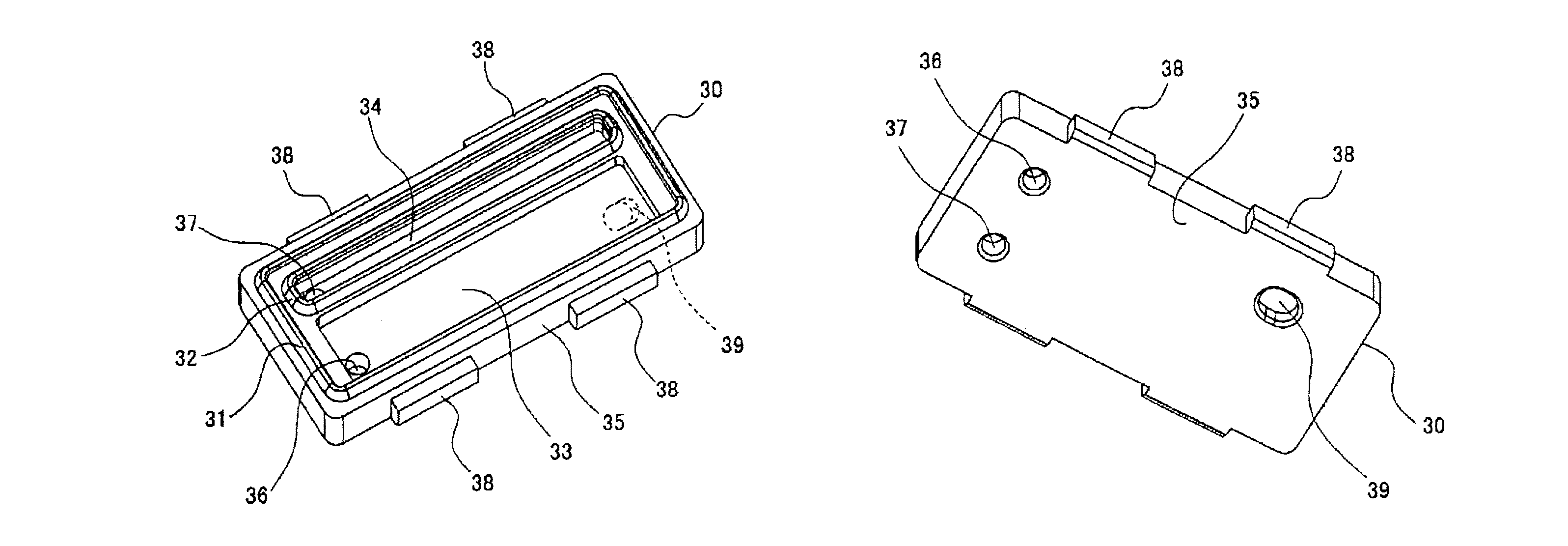
[0012]According to an embodiment of the invention, a cap member for covering a plurality of nozzle arrays formed through a nozzle plate of a liquid ejecting head comprises a first lip, at least one second lip, and a main body. The first lip has an annular shape and is configured to abut against the nozzle plate to enclose the plurality of nozzle arrays. The at least one second lip has an annular shape, is disposed within the annular first lip, and is configured to abut against the nozzle plate to enclose at least one of the plurality of nozzle arrays separately from the first lip. The first lip and the at least one second lip are disposed on the main body. The main body is configured to cooperate with the first lip and the at least one second lip to make sealing contact with the nozzle plate.
[0013]With this structure, the at least one second lip abuts against the nozzle plate within the first lip to enclose a portion of the plurality of nozzle arrays separately from the first lip. A portion of the at least one second lip, which is parallel with the nozzle arrays, abuts against the nozzle plate at a boundary portion defined between two adjacent nozzle arrays. Accordingly, an interval between the two adjacent nozzle arrays may be reduced. Consequently, the plurality of nozzle arrays may be arranged in higher density in the nozzle plate, thereby enabling a reduction in the size of the liquid ejecting head and production of the liquid ejecting head at reduced cost.
[0014]According to another embodiment of the invention, the above-described cap member may be incorporated into a liquid ejecting device. The liquid ejecting device comprises a liquid ejecting head that has a nozzle plate formed with a plurality of nozzle arrays and ejects a liquid from the nozzle arrays.
[0015]In this liquid ejecting device, withdrawal of liquid for restoring ejection performance of the nozzles may be performed by enclosing the nozzle arrays with the cap member, while reducing the amount of waste liquid. Further, the cap member allows the nozzle arrays to be arranged at relatively small intervals, enabling a reduction in the size of the liquid ejecting head, as well as the liquid ejecting device.
[0016]Other advantages of the present invention will be apparent to persons skilled in the art in view of the following

Problems solved by technology

In this case, if ink is withdrawn by covering all the nozzle arrays with a single lip, ink is withdrawn from all the nozzle arrays regardless of whether or not each nozzle array includes faulty nozzles, resulting in an increase in the amount of waste ink.
Nevertheless, in cap member 100, it may be difficult to make lips 101, 102 flush with each other.
Because a tool to cut such grooves passes the intersection (i.e., joint) twice, it is difficult to make the depth of the intersecting grooves the same, and a relatively small step may be formed at the bottoms of the intersecting grooves.
This measure, however, may require use of a greater power source and an increased rigidity of the inkjet recording device, leading to an increase in the production cost.

Method used


Image

  • Cap members and liquid ejecting devices comprising cap members
  • Cap members and liquid ejecting devices comprising cap members
  • Cap members and liquid ejecting devices comprising cap members

Examples


Embodiment Construction

[0036]Preferred embodiments of the present invention may be understood by referring to FIGS. 1-10, like numerals being used for like corresponding parts in the various drawings.

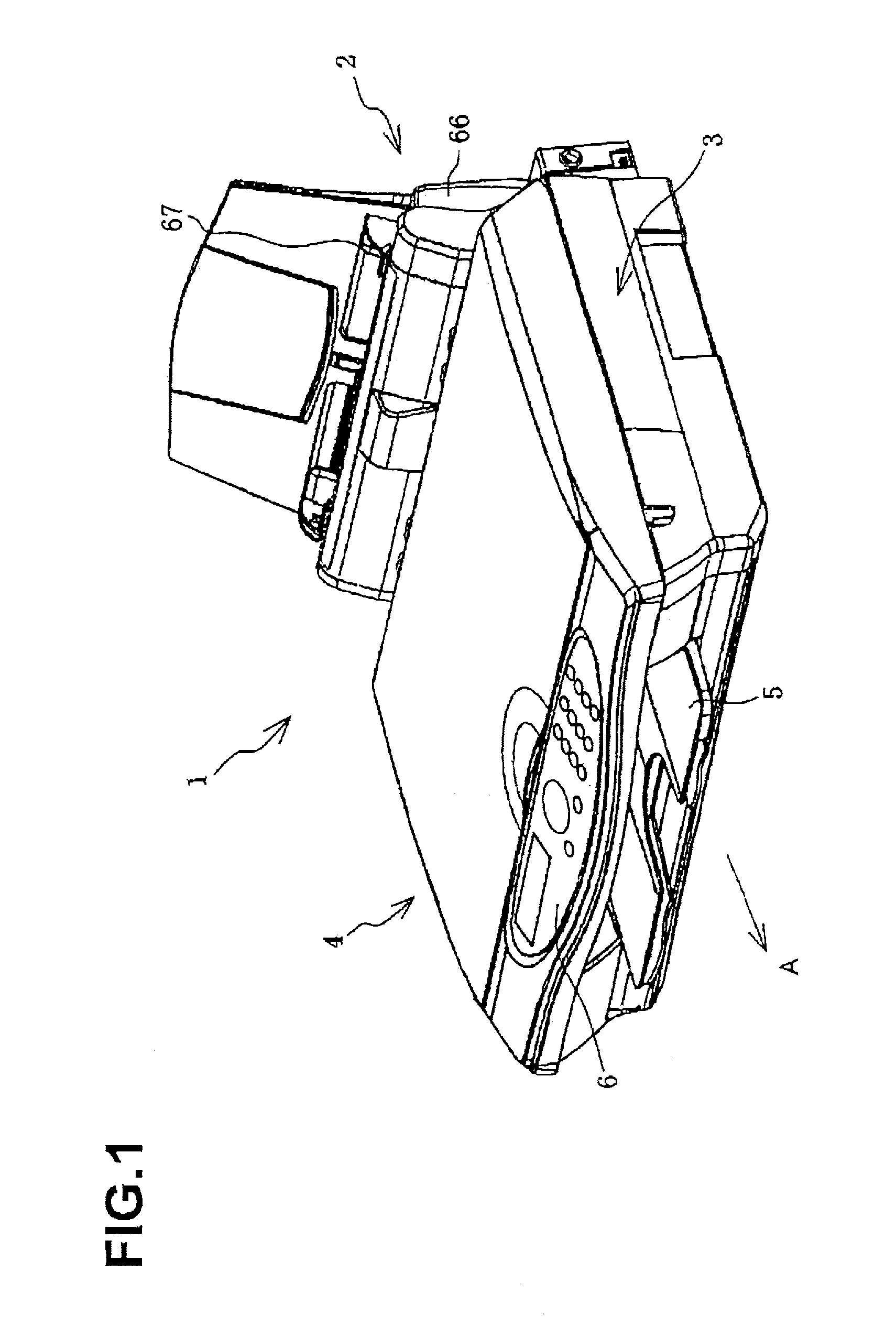
[0037]FIG. 1 shows a multifunction device 1 according to an embodiment of the present invention. Multifunction device 1 has printing, copying, scanning, facsimile, and telephone functions. As shown in FIG. 1, multifunction device 1 has a sheet feeder 2 at its rear, and has a printer 3 as an inkjet recording device at a front lower side of the sheet feeder 2. Further, multifunction device 1 has a reading unit 4 that performs copying, scanning, and facsimile functions. A discharged sheet tray 5 is disposed at a front side of printer 3, and an operation panel 6 is provided on an upper surface of a front end of reading unit 4.

[0038]Sheet feeder 2 is provided with an inclined wall portion 66 for supporting sheets at an inclined orientation, and a sheet guide 67 detachably attached to inclined wall portion 66 to gu...


PUM


Abstract

A cap member for covering a plurality of nozzle arrays disposed in a nozzle plate of a liquid ejecting head includes a first lip, at least one second lip, and a main body. The first lip has an annular shape and is configured to abut against the nozzle plate to enclose the plurality of nozzle arrays. At least one second lip has an annular shape, is disposed within the annular first lip, and is configured to abut against the nozzle plate to enclose at least one of the plurality of nozzle arrays separately from the first lip. The first lip and the at least one second lip are disposed on the main body. The main body is configured to cooperate with the first lip and the at least one second lip to make sealing contact with the nozzle plate.

Description

CROSS REFERENCE TO RELATED APPLICATION[0001]The present application claims priority from Japanese Patent Application No. 2005-099263 which was filed on Mar. 30, 2005, the disclosure of which is incorporated herein by reference in its entirety.BACKGROUND OF THE INVENTION[0002]1. Field of the Invention[0003]The present invention relates generally to a cap member for covering a plurality of nozzle arrays formed in a nozzle plate of a liquid ejecting head, and also relates generally to a liquid ejecting device comprising such a cap member.[0004]2. Description of Related Art[0005]As an example of liquid ejecting devices, inkjet recording devices capable of color recording using inks of a plurality of colors (such as black, yellow, cyan, and magenta) are known. In such known inkjet recording devices, arrays of nozzles for ejecting respective color inks are provided in a nozzle plate of an inkjet head. A cap member also is provided to enclose and cover the nozzle openings to prevent the in...

Claims


Application Information

Patent Timeline
Patent Type & Authority Patents(United States)
IPC IPC(8): B41J2/165
CPCB41J2/16508
Inventor SUZUKI, RYOHEITERADA, KOHEI
Owner BROTHER KOGYO KK
Learn More