Connector, a mating connector and a connector device

a technology of connectors and connectors, applied in the direction of coupling device connections, coupling protective earth/shielding arrangements, electrical appliances, etc., can solve the problems that watertight seals can also permit shaking, and achieve the effect of reducing transverse shaking

a technology of connectors and connectors, applied in the direction of coupling device connections, coupling protective earth/shielding arrangements, electrical appliances, etc., can solve the problems that watertight seals can also permit shaking, and achieve the effect of reducing transverse shaking

US7311546B2Inactive Publication Date: 2007-12-25SUMITOMO WIRING SYST LTD

Image

  • Connector, a mating connector and a connector device
  • Connector, a mating connector and a connector device
  • Connector, a mating connector and a connector device

Examples


Embodiment Construction

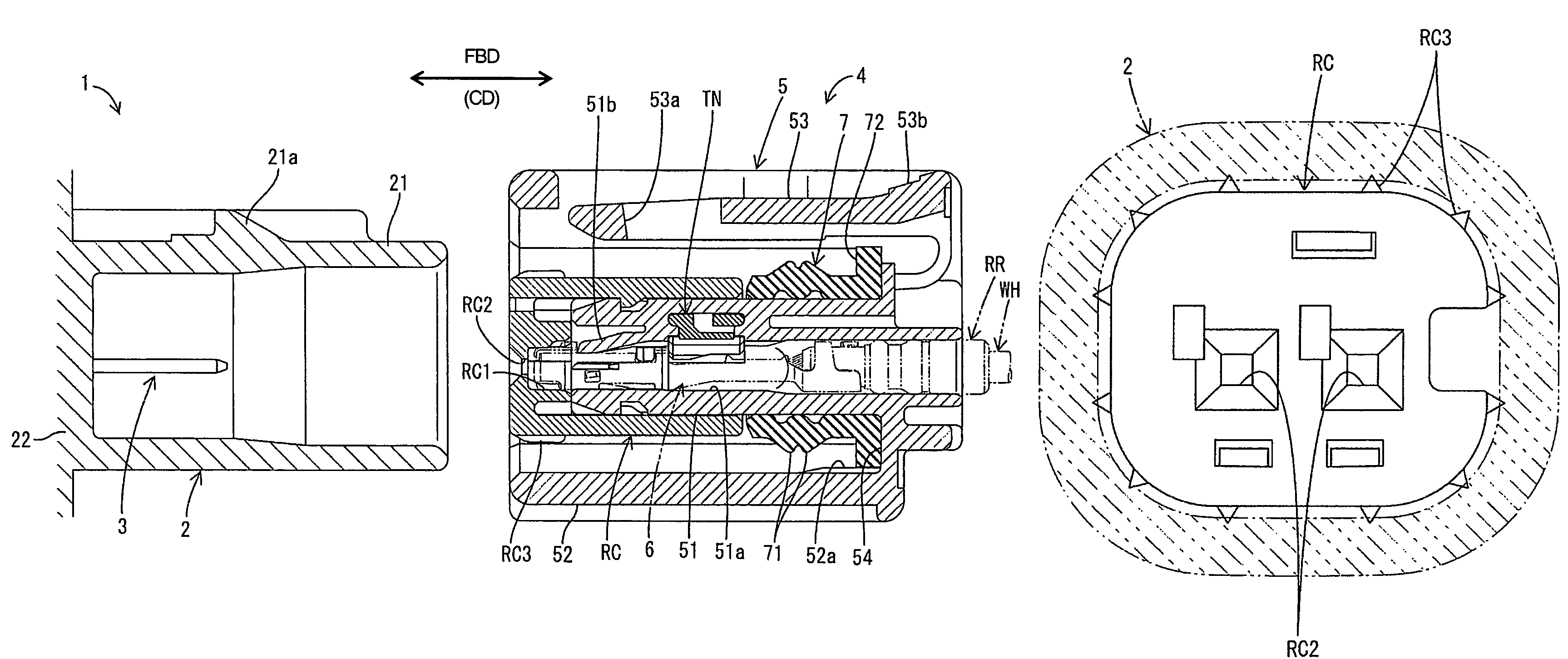
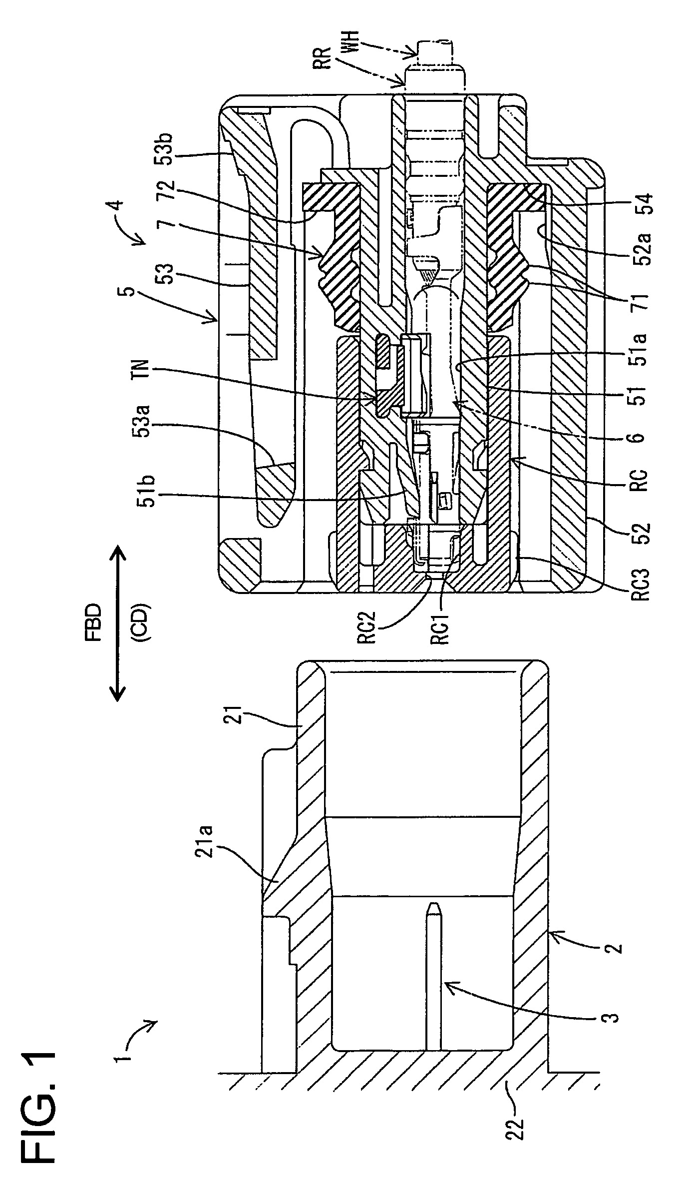
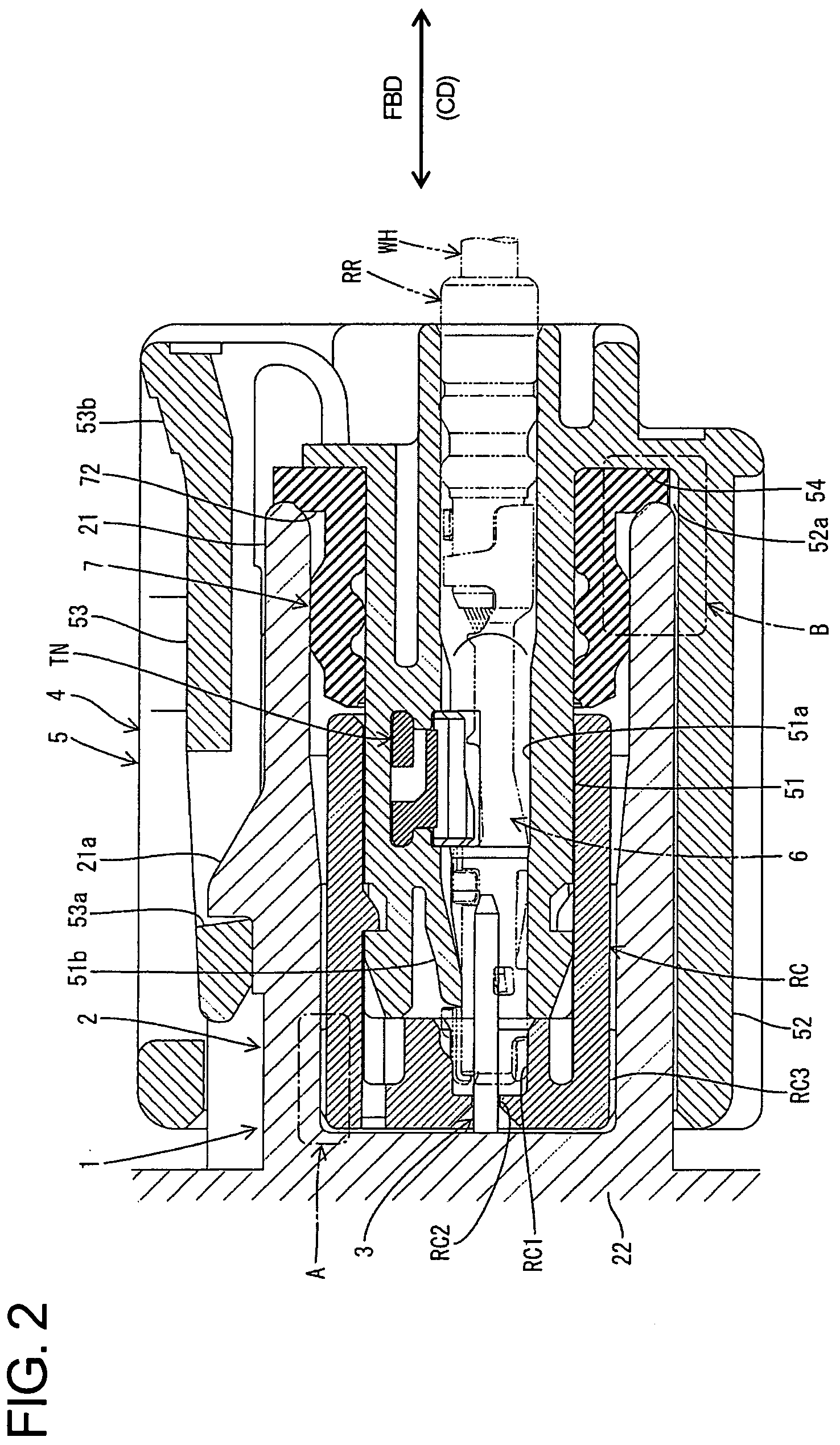
[0023]A connector assembly according to the invention comprises a male connector identified generally by the numeral 1 in FIGS. 1 to 4. The male connector 1 includes a male housing 2 and male terminals 3. The male housing 2 has a front end at the right side in FIG. 1. The connector assembly also includes a female connector 4 that is at the left in FIG. 1. The front ends of the connectors 1, 4 can be connected to one another, as shown in FIG. 2. In the following description, the transverse directions of the connectors 1, 4 extend up, down, left, right and obliquely in FIG. 5.

[0024]The male housing 2 is molded unitarily e.g. of a synthetic resin, and has a forwardly open tubular receptacle 21 that extends in forward and backward directions FBD along a connecting direction CD of the connectors 1, 4. The male housing 2 also has a terminal mounting portion 22 behind the receptacle 21. The inner peripheral surface of the receptacle 21 is wider at the front than at the back to define a div...


PUM


Abstract

A holding cap (RC) is mounted on a terminal holding portion (51) of a female housing (5) from the front, and a tubular cover (52) is so formed outward of the terminal holding portion (51) to surround the holding cap (RC). First shake preventing portions (RC3) project radially out from the outer surface of the front end of the holding cap (RC) and second shake preventing portions (52a) project in at the rear end of the inner surface of the cover (52). When male and female connectors (1, 4) are connected with each other, the first and second shake preventing portions (RC3, 52a) both contact a receptacle (21) of a male housing (2) to reduce the shaking between both housings (2, 5) in transverse directions.

Description

BACKGROUND OF THE INVENTION[0001]1. Field of the Invention[0002]The invention relates to a connector, to a mating connector and to a connector device provided with a pair of connectors engageable with each other.[0003]2. Description of the Related Art[0004]Japanese Examined Patent Publication No. H05-50113 discloses a connector assembly with first and second housings that are engageable with each other. A watertight seal is mounted in the first housing, and is held resiliently between the first and second housings and prevents the housings from shaking.[0005]The watertight seal of the above-described connector is resilient and can exert resilient forces to prevent the housing from shaking in a specified manner. However, the flexibility of the watertight seal also can permit shaking if a load on the housings exceeds the forces exerted by the seal.[0006]The invention was developed in view of the above problem and an object thereof is to provide an improved shake preventing function be...

Claims


Application Information

Patent Timeline
25 Dec 2007
Publication
US7311546B2
IPC
H01R13/648
CPC
H01R13/4364; H01R13/5219; H01R13/6272
Inventors
ITOU, TOMONARI