Multi-speed transmission with differential gear set and countershaft gearing

a technology of differential gear sets and gearing, applied in the direction of gearing, mechanical equipment, transportation and packaging, etc., can solve the problem of large number of gear pairs, and achieve the effect of reducing the number of countershaft gear sets and synchronizers

Inactive Publication Date: 2007-12-25
GM GLOBAL TECH OPERATIONS LLC
View PDF10 Cites 32 Cited by
  • Summary
  • Abstract
  • Description
  • Claims
  • Application Information

AI Technical Summary

Benefits of technology

[0003]A transmission is provided having a differential gear set with three input torque-transmitting mechanisms, such as friction clutches, to achieve torque flow through the differential gear set to a countershaft gearing arrangement utilizing power-on shifts. In comparison with a convention dual-clutch transmission, one of the input torque-transmitting mechanisms and the differential gear set are added. By utilizing the torque ratio of the differential gear set, additional torque ratios are available with good step progression, reducing the number of countershaft gear sets and synchronizers necessary in comparison to a dual-clutch transmission providing the same number of torque ratios. A shorter axial length is thus attainable.
[0008]In another aspect of the invention, a reverse torque ratio may be achieved utilizing a dedicated set of co-planar, intermeshing gears. However, in another embodiment, a reverse torque ratio is achieved by adding a synchronizer that selectively connects one of the members of the differential gear set to a stationary member to obtain a reverse torque ratio, thus eliminating the need for a dedicated set of intermeshing gears. Preferably, in the latter embodiment, the differential gear set is a double pinion planetary gear set and the additional synchronizer grounds the ring gear member to a stationary member such as the transmission housing.

Problems solved by technology

This necessitates a large number of required gear pairs, especially in transmissions that have a relatively large number of forward speed ratios.

Method used


Image

  • Multi-speed transmission with differential gear set and countershaft gearing
  • Multi-speed transmission with differential gear set and countershaft gearing
  • Multi-speed transmission with differential gear set and countershaft gearing

Examples


second embodiment

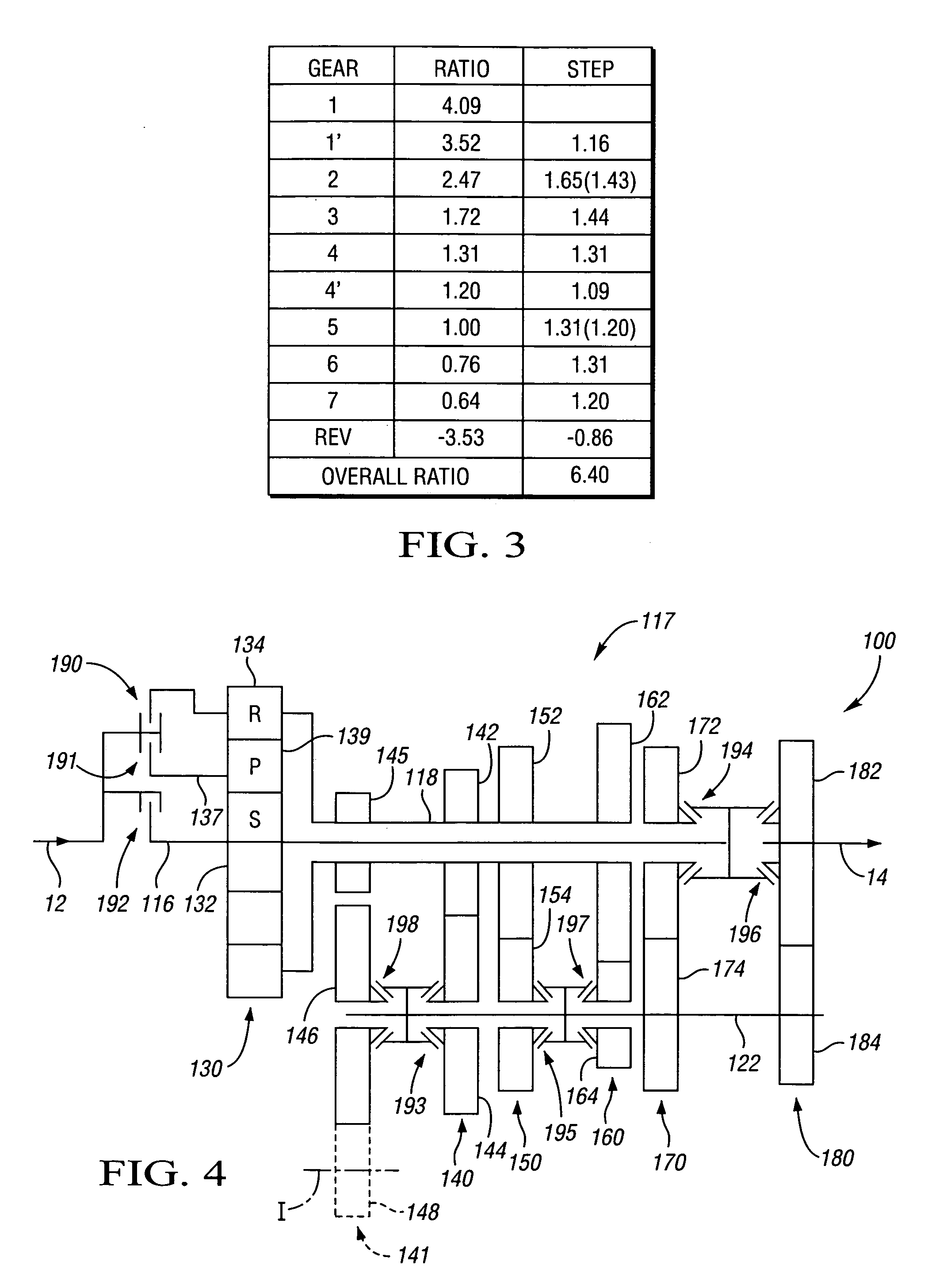
[0041]Referring to FIG. 4 a multi-speed transmission 100 is depicted. The transmission 100 includes an input member 12 and an output member 14. In this embodiment, the input member 12 and the output member 14 are shafts, and will be referred to as such. Those skilled in the art will appreciate that the input and output members 12, 14 may be components other than shafts. The input shaft 12 is continuously connected with an engine (not shown). The output shaft 14 is continuously connected with the final drive unit (not shown). The transmission 100 includes a countershaft gearing arrangement 117 that includes intermediate shafts, a countershaft, co-planar intermeshing gear sets and selectively engagable synchronizers as will be described herein. For instance, the countershaft gearing arrangement 117 includes an intermediate shaft 116 and an intermediate shaft 118, which is a sleeve shaft concentric with the intermediate shaft 116. The intermediate shafts 118 and 116 are referred to in ...

third embodiment

[0050]Referring to FIG. 5 a multi-speed transmission 200 is depicted. The transmission 200 includes an input member 12 and output member 14. In this embodiment, the input member 12 and the output member 14 are shafts, and will be referred to as such. Those skilled in the art will appreciate that the input and output members 12, 14 may be components other than shafts. The input shaft 12 is continuously connected with an engine (not shown). The output shaft 14 is continuously connected with the final drive unit (not shown). The transmission 200 includes a countershaft gearing arrangement 217 that includes intermediate shafts, countershafts, co-planar intermeshing gear sets and selectively engagable synchronizers as will be described herein. For instance, the countershaft gearing arrangement 217 includes an intermediate shaft 216 and an intermediate shaft 218, which is a sleeve shaft concentric with the intermediate shaft 216. The intermediate shafts 218 and 216 are referred to in the ...

fourth embodiment

[0061]Referring to FIG. 8, a multi-speed transmission 300 is depicted. The transmission 300 includes an input member 12 and output member 14. In this embodiment, the input member 12 and the output member 14 are shafts, and will be referred to as such. Those skilled in the art will appreciate that the input and output members 12, 14 may be components other than shafts. The input shaft 12 is continuously connected with an engine (not shown). The output shaft 14 is continuously connected with the final drive unit (not shown). The transmission 300 includes a countershaft gearing arrangement 317 that includes intermediate shafts, a countershaft, co-planar intermeshing gear sets and selectively engagable synchronizers as will be described herein. For instance, the countershaft gearing arrangement 317 includes an intermediate shaft 316 and an intermediate shaft 318, which is a sleeve shaft concentric with the intermediate shaft 316. The intermediate shafts 318 and 316 are referred to in th...


PUM


Abstract

A transmission is provided having a differential gear set with three input torque-transmitting mechanisms, such as friction clutches, to achieve torque flow through the differential gear set to a countershaft gearing arrangement. The transmission utilizes power-on shifts. By utilizing the torque ratio of the differential gear set, additional forward ratios are available with good step progression, reducing the number of countershaft gear sets and synchronizers necessary in comparison to a dual-clutch transmission providing the same number of ratios. A shorter axial length is thus attainable.

Description

TECHNICAL FIELD[0001]The invention relates to a multi-speed transmission having both a differential gear set and a countershaft gearing arrangement.BACKGROUND OF THE INVENTION[0002]A typical multi-speed, dual clutch transmission uses a combination of two friction clutches and several dog clutch / synchronizers to achieve “power-on” or dynamic shifts by alternating between one friction clutch and the other, with the synchronizers being “pre-selected” for the oncoming ratio prior to actually making the dynamic shift. “Power-on” shifting means that torque flow from the engine need not be interrupted prior to making the shift. This concept typically uses countershaft gears with a different, dedicated gear pair or set to achieve each forward speed ratio (with the exception of being able to achieve a direct drive ratio in a rear wheel drive application). Accordingly, the total number of gears required in this typical design is two times the number of forward speeds, plus three for reverse. ...

Claims


Application Information

Patent Timeline
Patent Type & Authority Patents(United States)
IPC IPC(8): F16H37/08F16H3/44F16H37/02
CPCF16H37/0833F16H2003/0931F16H2200/0056Y10T74/19233F16H2200/0065
Inventor BORGERSON, JAMES B.
Owner GM GLOBAL TECH OPERATIONS LLC
Why Eureka
Try Eureka