Force-sensing bearing

a technology of force-sensing bearings and bearings, applied in the direction of force measurement by elastic gauge deformation, instruments, force/torque/work measurement apparatus, etc., can solve problems such as the shift of pressure ellips

Inactive Publication Date: 2008-01-08
INA SCHAEFFLER KG
View PDF11 Cites 151 Cited by
  • Summary
  • Abstract
  • Description
  • Claims
  • Application Information

AI Technical Summary

Problems solved by technology

This also results in a shift in the pressure ellipse between rolling bearing ring and rolling body in the axial direction.

Method used


Image

  • Force-sensing bearing
  • Force-sensing bearing
  • Force-sensing bearing

Examples


Embodiment Construction

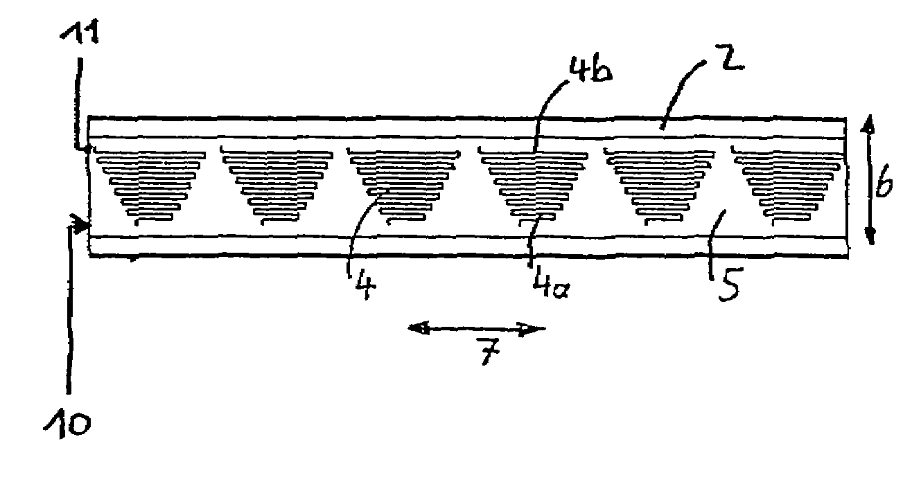
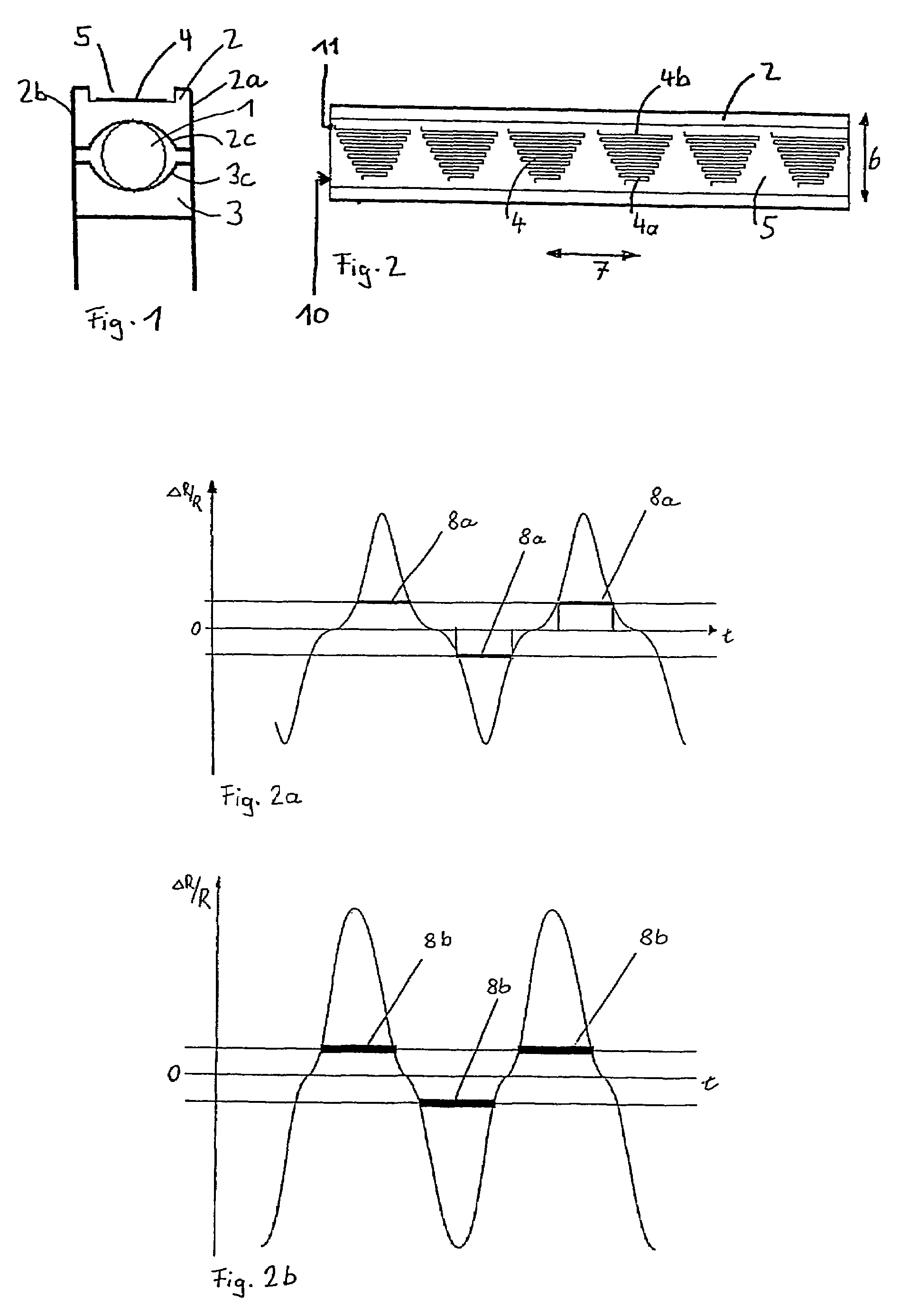
[0012]FIG. 1 illustrates a rolling bearing comprising curved raceways (here a deep-groove ball bearing). The rolling body 1 is arranged between the two races 2 and 3. In this illustration, the rolling body is situated precisely in the central position of the rolling bearing. In the event of loading in an axial direction the rolling body migrates in the axial direction toward the other side area 2a or 2b of the rolling bearing, depending on the force direction of the axial forces. In this example, sensors 4 are arranged in a groove 5 on the outer ring 2. The analogous arrangement of the sensors 4 in a groove on the inner ring 3 is not illustrated.

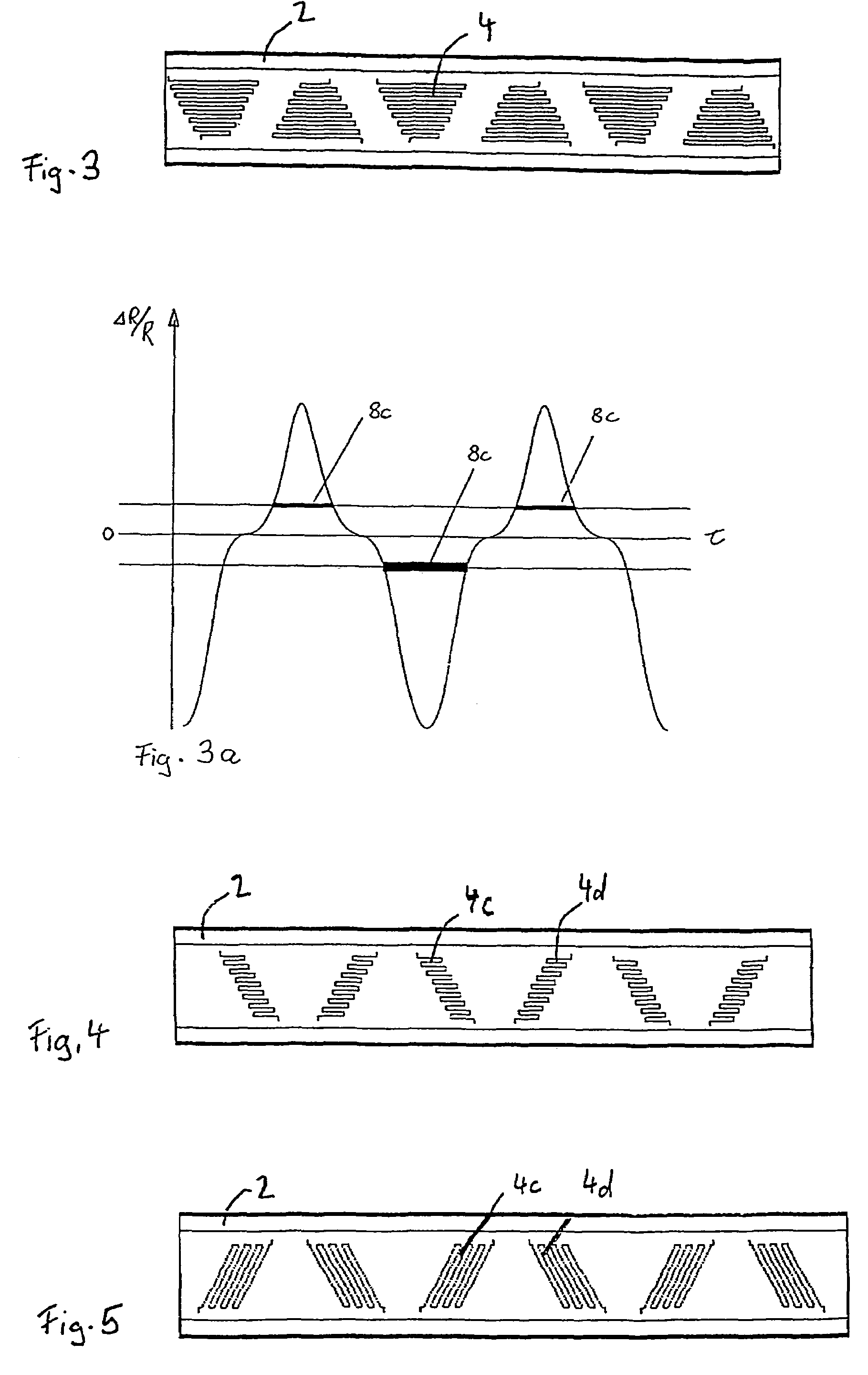
[0013]FIGS. 2 to FIG. 5 show special sensor arrangements arranged in the groove 4 on the outer ring 2 and / or on the inner ring 3. In order to better discern the arrangement of the sensors, the rolling bearing races are shown unwound in the illustration. The sensors 4 are illustrated in trapezoidal arrangement here in the preferred embodiment...


PUM

PropertyMeasurementUnit
outer diameteraaaaaaaaaa
forceaaaaaaaaaa
inner diameteraaaaaaaaaa

Abstract

The invention relates to a roller bearing comprising curved running paths, in addition to roller bodies and strain gauge sensors which are arranged between said running paths, said sensors being located in a groove on the outer diameter of the outer ring and / or on the inner diameter of the inner ring. The length of two adjacent strip conductor sections of the strain gauge sensor varies in such a way as to measure the angular position of the roller bodies between the strip conductors.

Description

CROSS REFERENCE TO RELATED APPLICATION[0001]The present application is a 35 U.S.C. §§ 371 national phase conversion of PCT / DE2003 / 003829 filed 19 Nov. 2003, which claims priority of German Application No. 102 54 814.5 filed 23 Nov. 2002. The PCT International Application was published in the German language.BACKGROUND OF THE INVENTION[0002]The invention relates to a rolling bearing comprising arranged sensors by means of which the present loading on the rolling bearing can be determined.[0003]U.S. Pat. No. 5,952,587 describes such force-sensing bearings. FIG. 10b of this document illustrates how, in the case of a tapered roller bearing, the force (material elongation) measured by the sensors is divided into radial forces and axial forces. The problem of this solution is that the raceway angle has to be constant in order to decompose the forces into radial and axial forces. For rolling bearings comprising curved raceways, such as e.g. deep-groove ball bearings, the method described c...

Claims


Application Information

Patent Timeline
Patent Type & Authority Patents(United States)
IPC IPC(8): G01L5/12G01L1/22G01L1/00G01L5/00G01M13/04
CPCG01L5/0019G01M13/04F16C19/522F16C33/586
Inventor VAN DER KNOKKE, HENRIWUNDERLICH, RAINERHAUSER, KARINHOLLWECK, ROMAN
Owner INA SCHAEFFLER KG
Why Eureka
Try Eureka