Nailing depth control structure for a palm nailer

a control structure and nailing technology, applied in the field of palm nailers, can solve the problems of difficult identification and inconvenient operation, and achieve the effect of improving efficiency and avoiding the disadvantage of difficult identification

Active Publication Date: 2008-01-08
BASSO IND CORP
View PDF18 Cites 16 Cited by
  • Summary
  • Abstract
  • Description
  • Claims
  • Application Information

AI Technical Summary

Benefits of technology

[0013]As compared to prior art, the present invention has enhanced efficacy. In the prior art, the nailing depth of a common palm nailer is controlled with a structural design of belleville springs that is mounted between a screw terminal of the extension sleeve and screwing slot of a nailer body. However, it has disadvantages of difficult identification and inconvenient operation due to required removal of extension sleeve.
[0014]The present invention includes a special structure comprising a control block 40 with several steps, a cylinder base 50, a flexible pipe 60 fitted with an anchoring position 65, a resilient component 70 and a rotary locating component 80. When the user employs the present invention, it is possible to drive the synchronous rotation of flexible pipe 60 by quickly rotating the cylinder base. So, the position of anchoring position 65 is allowed to change within the flexible pipe 60 in relation to step 41, 42, 43 of control block 40, thereby adjusting a retracted distance of flexible pipe 65 for control of nailing depth (i.e. nail head is protruded, flush or retracted). By using scale markers D1, D2 (as illustrated in FIG. 21) placed externally at a cylinder base 50, it is feasible to identify the current nailing depth of palm nailer, and relieve the need of removing structural components with improved efficiency.
[0015]As a whole, the nailing depth control structure for a palm nailer of the present invention can improve efficiently the shortcomings of conventional structures and provide a simple operation and identification.

Problems solved by technology

However, it has disadvantages of difficult identification and inconvenient operation due to required removal of extension sleeve.

Method used


Image

  • Nailing depth control structure for a palm nailer
  • Nailing depth control structure for a palm nailer
  • Nailing depth control structure for a palm nailer

Examples


Embodiment Construction

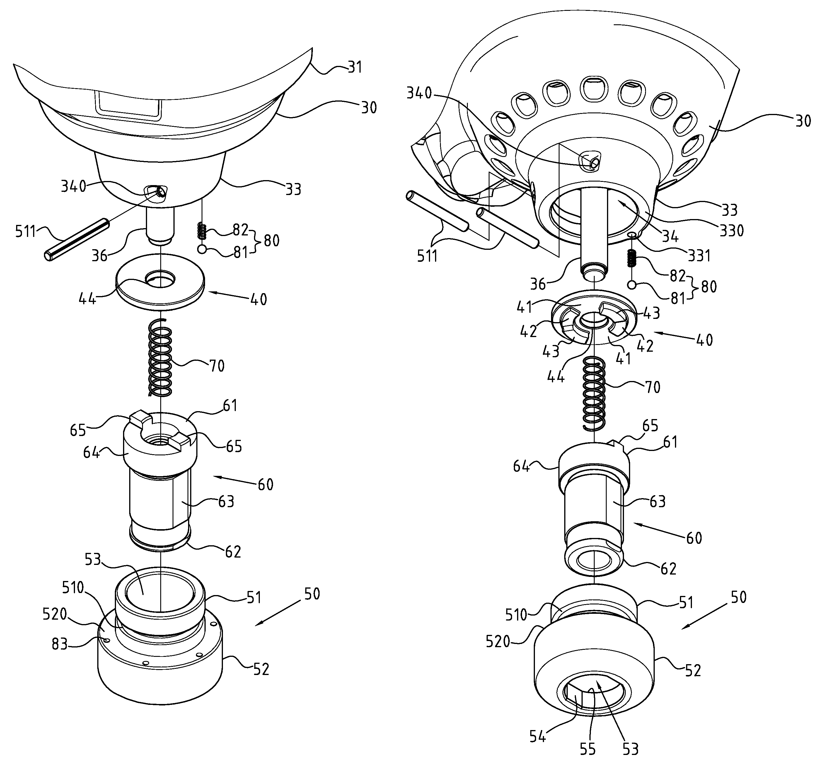
[0035]Referring to FIGS. 5, 6, 7, 8, 9, the nailing depth control structure of palm nailer has the present detailed description of the present invention based on a typical preferred embodiment. Although the invention has been explained in relation to a preferred embodiment, it is to be understood that many other possible modifications and variations can be made without departing from the spirit and scope of the invention as hereinafter claimed.

[0036]A palm nailer generally comprises a palm nailer body 30, as shown in FIG. 5, which comprises a holding portion 31, an air inlet 32 and a hammering head 33. The hammering head 33 is provided with an assembly slot 34, which has a through hole 35 for protruding of a hammer axle 36 within hammering head 33.

[0037]The invention also includes a control block 40, which is placed into assembly slot 34 of hammering head 33. At least two steps are placed externally onto control block 40 along a preset peripheral line. In this preferred embodiment, ...


PUM


Abstract

The nailing depth control structure for a palm nailer is mounted at the hammering head of the palm nailer. The control structure includes a control block with several steps, a cylinder base, a flexible pipe fitted internally with an anchoring position, a resilient component and a rotary location component. When the user employs the present invention, it is possible to drive the synchronous rotation of flexible pipe and change the position of anchoring position of flexible pipe in relation to steps of control block, thereby adjusting retracted distance of flexible pipe for easy control of nailing depth. By using scale markers placed externally at the cylinder base, it is feasible to identify the current nailing depth of palm nailer, and relieve the need of removing structural components with improved efficiency and ease-of-operation.

Description

RELATED U.S. APPLICATIONS[0001]Not applicable.STATEMENT REGARDING FEDERALLY SPONSORED RESEARCH OR DEVELOPMENT[0002]Not applicable.REFERENCE TO MICROFICHE APPENDIX[0003]Not applicable.FIELD OF THE INVENTION[0004]The present invention relates generally to a palm nailer, and more particularly to an innovative palm nailer with a nailing depth control structure.BACKGROUND OF THE INVENTION[0005]Unlike a conventional nailer, the palm nailer of the present invention is a pneumatic handheld nailing tool, which is specifically designed with a holding position for the palm. With the exclusion of the nailing spike, this structure is provided with a single nailing body that is fixed into a work piece by means of hammering.[0006]The structure of a prior art palm nailer is illustrated in FIG. 1, wherein the bottom of nailer body 10 is screwed with an extension sleeve 11, and wherein the bottom of the extension sleeve 11 is fitted with a flexible pipe 12. A spring 14 is mounted between the top of t...

Claims


Application Information

Patent Timeline
Patent Type & Authority Patents(United States)
IPC IPC(8): B25C7/00
CPCB25C1/008B25C1/04
Inventor CHEN, JING-HUNG
Owner BASSO IND CORP
Why Eureka
Try Eureka