Dust collector

a dust collector and dust collector technology, applied in the direction of chemistry apparatus and processes, vapor flow control, colloidal chemistry, etc., can solve the problems of difficult collection of dust by the electric dust collector, weak coulomb's force acting thereon, and difficult charge of small particles, etc., to achieve efficient collection, efficiently generated, and efficient collection

Active Publication Date: 2008-01-08
MITSUBISHI HITACHI POWER SYSTEMS ENVIRONMENTAL SOLUTIONS LTD
View PDF31 Cites 26 Cited by
  • Summary
  • Abstract
  • Description
  • Claims
  • Application Information

AI Technical Summary

Benefits of technology

[0013]The present invention has been achieved in order to solve the above problems. It is an object of the present invention to provide a dust collecting apparatus that uses the secondary flow induced by the ion wind for the flow rate of the main gas in a wide range, to convect the gas in the flow path, thereby efficiently collecting the particulate matter contained in the gas.

Problems solved by technology

However, particles having a small particle diameter are hard to be charged, and hence the Coulomb's force acting thereon is also weak.
Furthermore, the particles having a small particle diameter have essentially a property such that the behavior thereof is governed by air flow (particles moves together with the air flow along the stream line of the air flow), and hence, collection thereof by the electric dust collecting apparatus is difficult.

Method used


Image

  • Dust collector
  • Dust collector
  • Dust collector

Examples


first embodiment

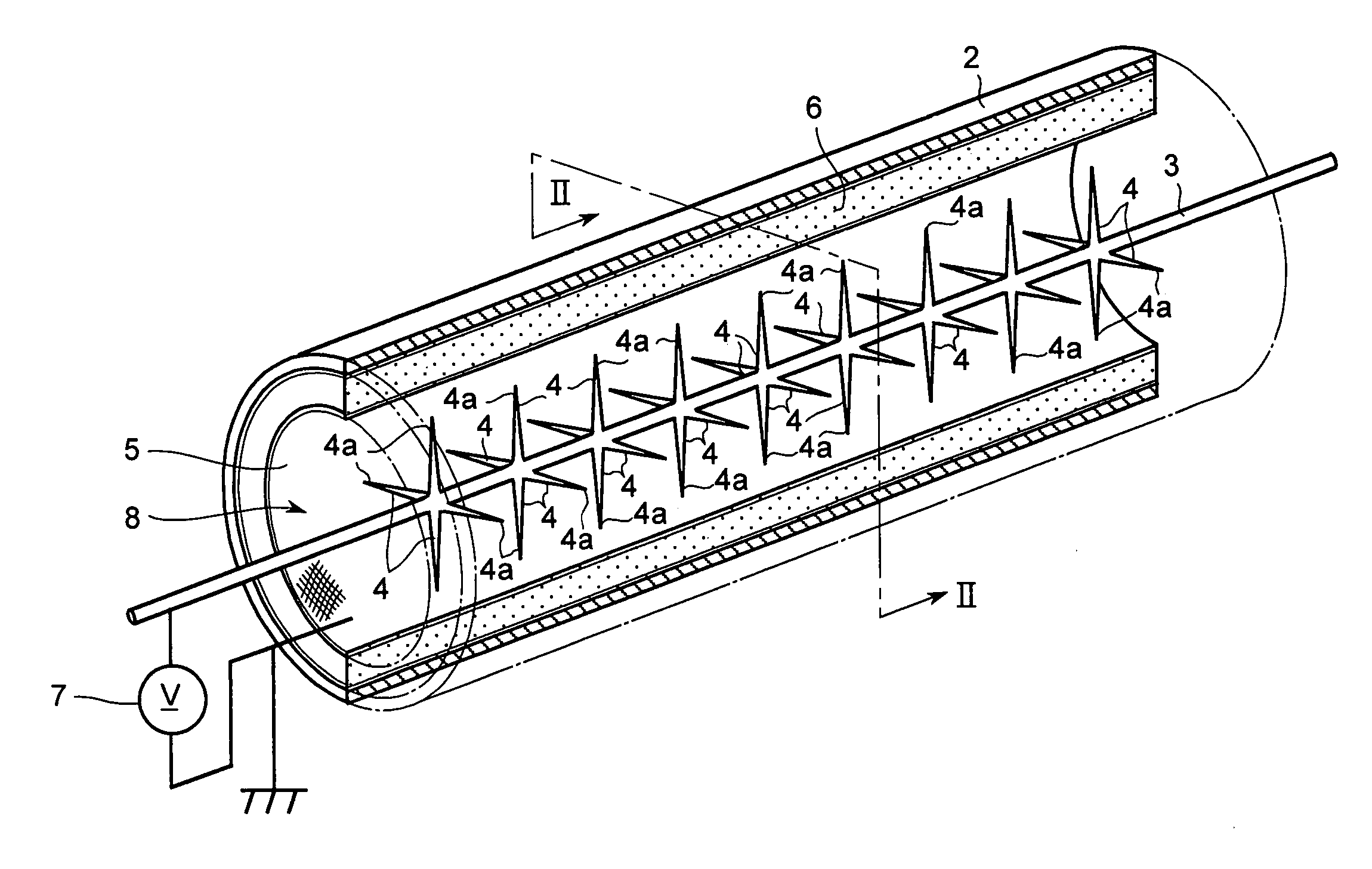
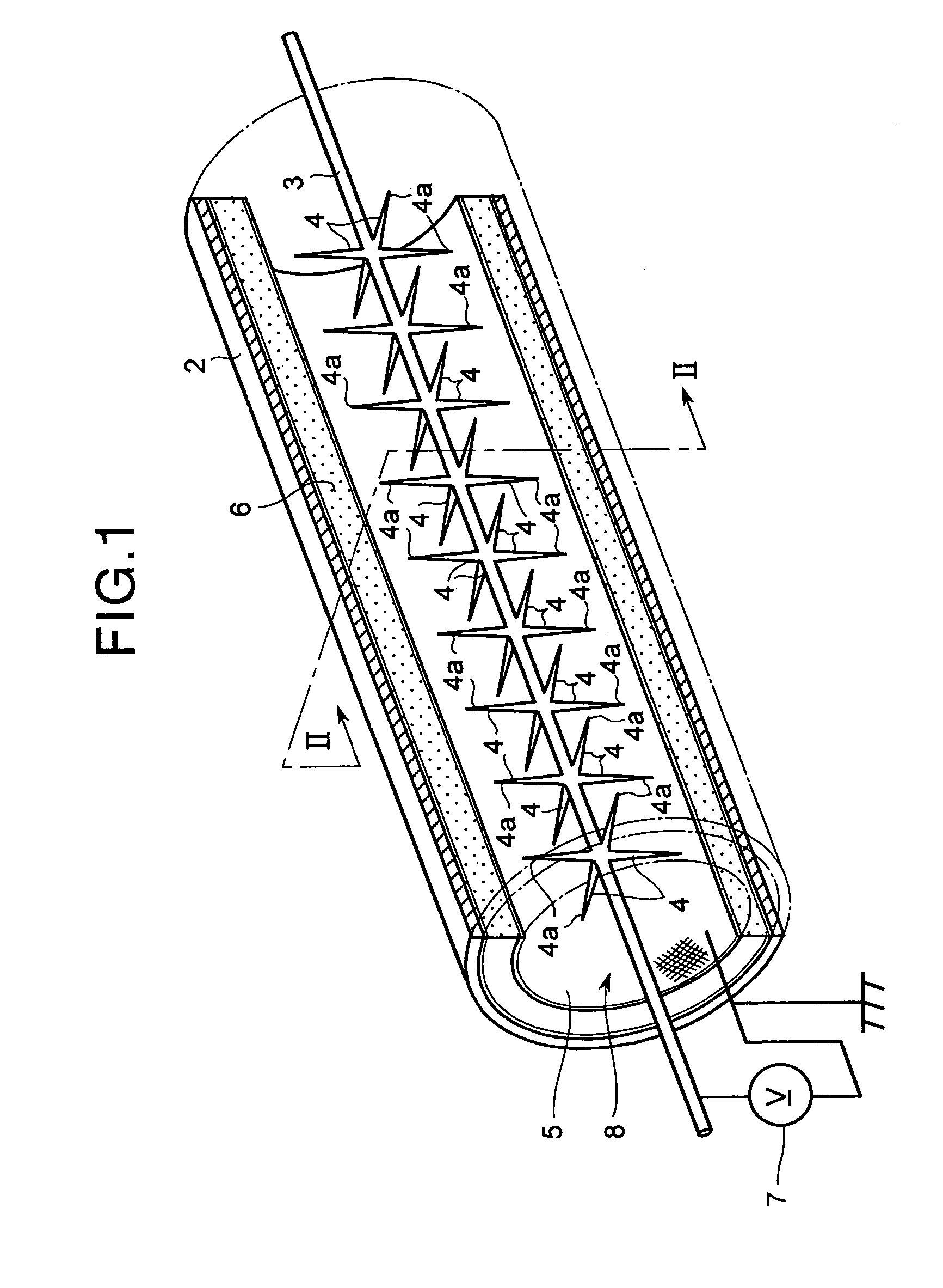
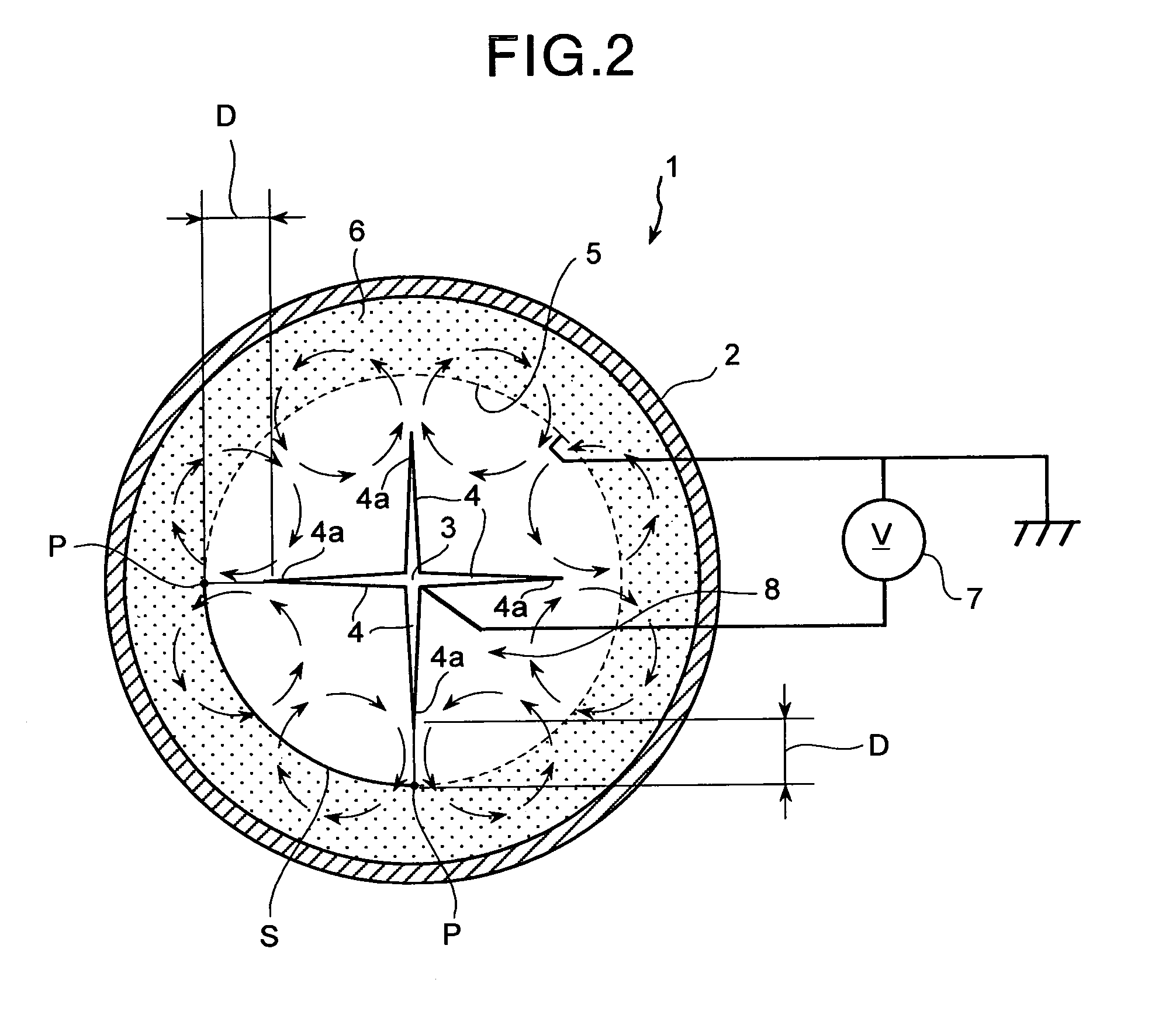
[0072]FIG. 1 is a perspective view of a part of a dust collecting apparatus according to the present invention in cross section, and FIG. 2 is a cross section along the line II-II in FIG. 1.

[0073]In the first embodiment, as shown in FIGS. 1 and 2, a dust collecting apparatus 1 includes an outer shell 2, a discharge electrode that becomes a main part 3 or a discharge unit 4, a ground electrode 5, a dust-collecting filter layer 6, and a power supply 7.

[0074]The outer shell 2 is in a cylindrical shape, and forms a flow path 8 through which a gas containing particulate matter therein flows. The main part 3 of the discharge electrode extending along the direction of a flow path is arranged at the center of the flow path 8. The discharge unit 4 of the discharge electrode is formed in a thorn shape extending from the main part 3 of the discharge electrode toward the ground electrode 5 in a direction transverse to the flow path 8.

[0075]Tips 4a of the discharge units 4 of the discharge elect...

second embodiment

[0093]In the second embodiment, as shown in FIGS. 3 and 4, the dust collecting apparatus 1 includes a plurality of main parts 3 of the discharge electrode. These main parts 3 of the discharge electrode are arranged away from each other in the direction transverse to the flow path 8, and extend along the flow path 8. The main parts 3 of the discharge electrode are arranged in a row in the direction transverse to the flow path 8. The ground electrodes 5 are arranged in parallel with the discharge electrodes, with the row of the main parts 3 of the discharge electrode put therebetween.

[0094]The discharge units 4 of the discharge electrode are formed in a thorn shape extending from the respective main parts 3 of the discharge electrode toward the ground electrodes ground electrode 5 on the opposite sides, and provided at a plurality of positions on the respective main parts 3 of the discharge electrode. The tips 4a of the discharge units 4 of the discharge electrode provided on the adja...

third embodiment

[0097]FIG. 5 is a perspective view of a part of the dust collecting apparatus according to the present invention in cross section, and FIG. 6 is a cross section along the line VI-VI in FIG. 5. Like reference signs are designated with like members having the same function as in the above embodiments and the redundant explanation is omitted.

[0098]In the third embodiment, as shown in FIGS. 5 and 6, the dust collecting apparatus 1 includes a plurality of main parts 3 of the discharge electrode as in the dust collecting apparatus 1 according to the second embodiment. These main parts 3 of the discharge electrode are arranged away from each other in the direction along the flow path 8, and extend in the direction transverse to the flow path 8. The discharge units 4 of the discharge electrode extending from the main part 3 of the discharge electrode toward the ground electrodes are provided at a plurality of positions on the respective main parts 3 of the discharge electrode.

[0099]It is pr...


PUM


Abstract

An apparatus, which collects particulate matter contained in a gas flowing through a flow path formed in a cylindrical shape having an outer surface and an inner surface, includes: an outer shell that forms the outer surface of the flow path; a ground electrode that forms the inner surface of the flow path; a filter layer that is arranged between the outer shell and the ground electrode; and a discharge electrode that generates, when a voltage is applied, an ion wind inducing a secondary flow toward the ground electrode in a direction transverse to the flow path. The secondary flow passes through the ground electrode and the filter layer having a predetermined aperture ratio.

Description

[0001]This application is the national stage application of International Application No. PCT / JP04 / 12288, filed on Aug. 26, 2004.TECHNICAL FIELD[0002]The present invention relates to a dust collecting apparatus that generates a secondary flow, in a flow path through which a gas containing particulate matter flows, by an ion wind in a direction orthogonal to the gas flow, to collect the particulate matter in the gas.BACKGROUND ART[0003]As a method of collecting and removing the particulate matter from the gas, an electric dust collecting apparatus is well known. The dust collecting apparatus collects the particulate matter charged by corona discharge occurring in the gas onto a dust collection electrode installed in the gas by the Coulomb's force.[0004]Since particles having a large particle diameter have a large charge amount, those particles can be easily collected on the dust collection electrode by the Coulomb's force. However, particles having a small particle diameter are hard ...

Claims


Application Information

Patent Timeline
Patent Type & Authority Patents(United States)
IPC IPC(8): B03C3/36B03C3/41B03C3/49B03C3/51
CPCB03C3/41B03C3/49B03C3/51B03C2201/10Y10S55/38B03C2201/14B03C3/40
Inventor TOMIMATSU, KAZUTAKANAGATA, CHIKAYUKIKAGAMI, MORIOUEDA, YASUTOSHI
Owner MITSUBISHI HITACHI POWER SYSTEMS ENVIRONMENTAL SOLUTIONS LTD
Why Eureka
Try Eureka