Dust collector
- Summary
- Abstract
- Description
- Claims
- Application Information
AI Technical Summary
Benefits of technology
Problems solved by technology
Method used
Image
Examples
first embodiment
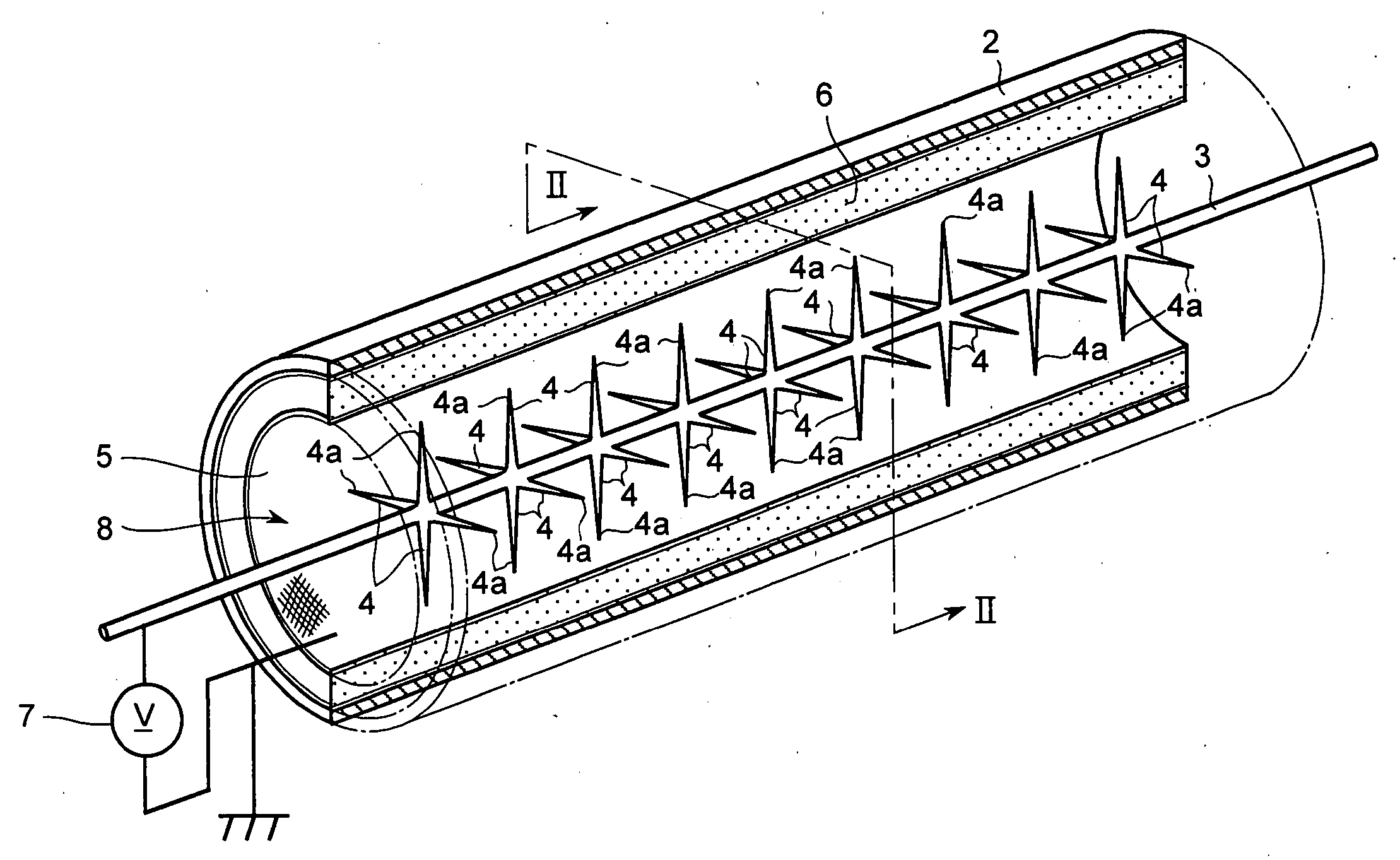
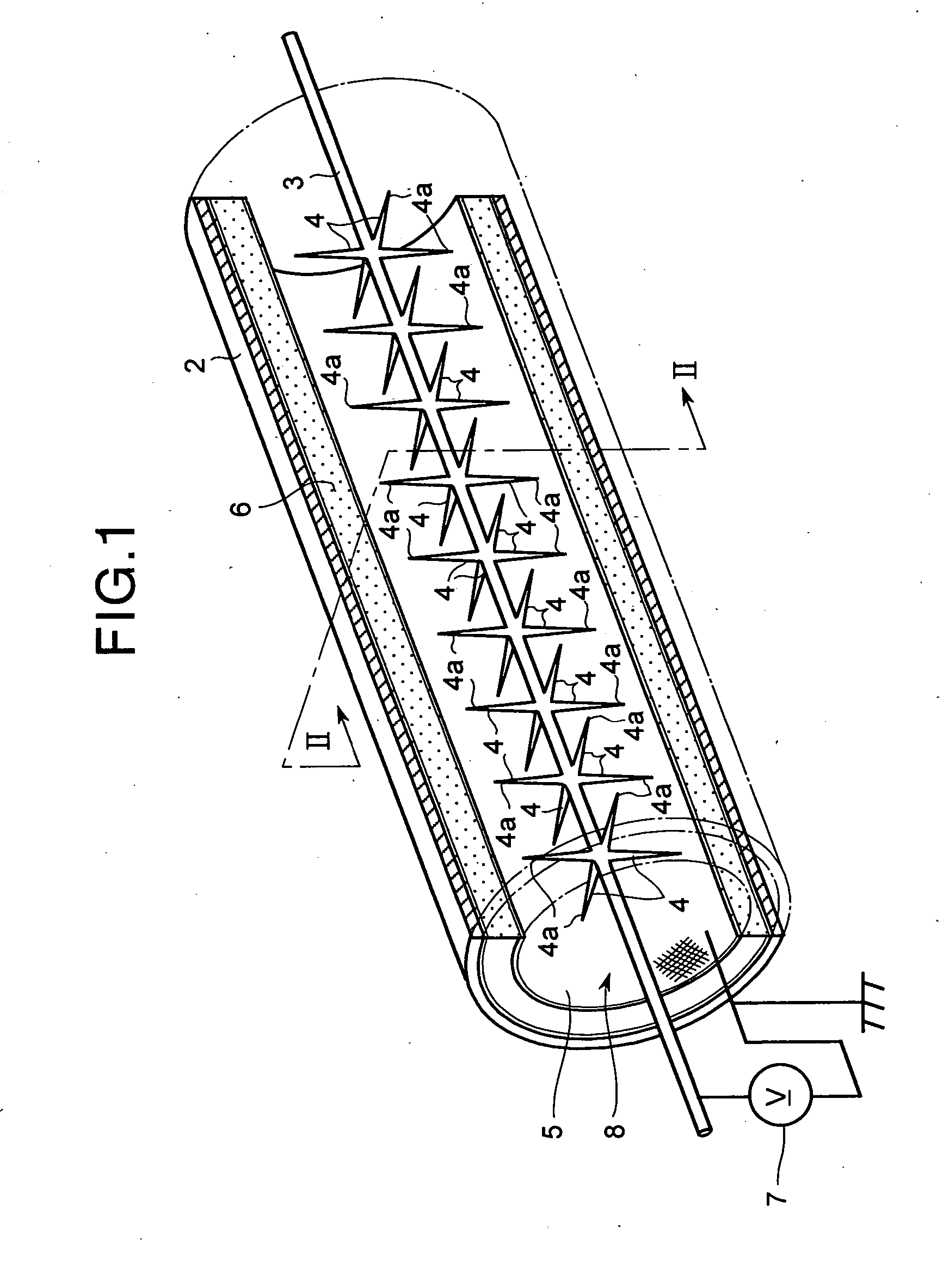
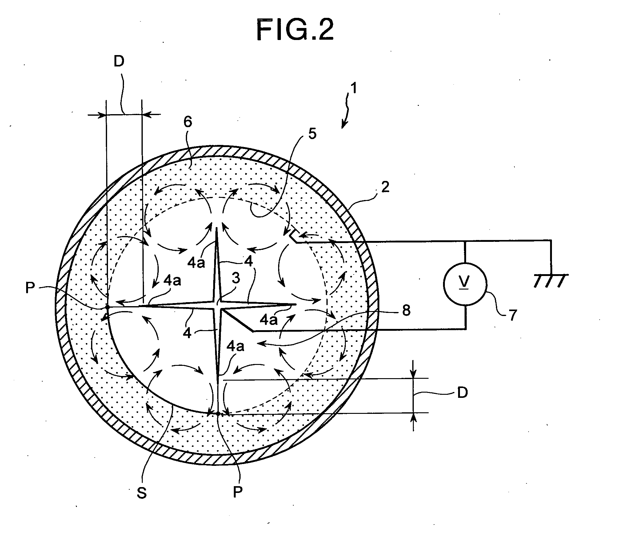
[0074]FIG. 1 is a perspective view of a part of a dust collecting apparatus according to a first embodiment of the present invention in cross section, and FIG. 2 is a cross section along the line II-II in FIG. 1.
[0075] In the first embodiment, as shown in FIGS. 1 and 2, a dust collecting apparatus 1 includes an outer shell 2, a discharge electrode that becomes a main part 3 or a discharge unit 4, a ground electrode 5, a dust-collecting filter layer 6, and a power supply 7.
[0076] The outer shell 2 is in a cylindrical shape, and forms a flow path 8 through which a gas containing particulate matter therein flows. The main part 3 of the discharge electrode extending along the direction of a flow path is arranged at the center of the flow path 8. The discharge unit 4 of the discharge electrode is formed in a thorn shape extending from the main part 3 of the discharge electrode toward the ground electrode 5 in a direction transverse to the flow path 8.
[0077] Tips 4a of the discharge un...
second embodiment
[0094]FIG. 3 is a perspective view of a part of the dust collecting apparatus according to a second embodiment of the present invention in cross section, and FIG. 4 is a cross section along the line IV-IV in FIG. 3. Like reference signs are designated with like members having the same functions as in the first embodiment, and the redundant explanation is omitted.
[0095] In the second embodiment, as shown in FIGS. 3 and 4, the dust collecting apparatus 1 includes a plurality of main parts 3 of the discharge electrode. These main parts 3 of the discharge electrode are arranged away from each other in the direction transverse to the flow path 8, and extend along the flow path 8. The main parts 3 of the discharge electrode are arranged in a row in the direction transverse to the flow path 8. The ground electrodes 5 are arranged in parallel with the discharge electrodes, with the row of the main parts 3 of the discharge electrode put therebetween.
[0096] The discharge units 4 of the disc...
third embodiment
[0099]FIG. 5 is a perspective view of a part of the dust collecting apparatus according to a third embodiment of the present invention in cross section, and FIG. 6 is a cross section along the line VI-VI in FIG. 5. Like reference signs are designated with like members having the same function as in the above embodiments and the redundant explanation is omitted.
[0100] In the third embodiment, as shown in FIGS. 1 and 2, the dust collecting apparatus 1 includes a plurality of main parts 3 of the discharge electrode as in the dust collecting apparatus 1 according to the second embodiment. These main parts 3 of the discharge electrode are arranged away from each other in the direction along the flow path 8, and extend in the direction transverse to the flow path 8. The discharge units 4 of the discharge electrode extending from the main part 3 of the discharge electrode toward the ground electrodes are provided at a plurality of positions on the respective main parts 3 of the discharge ...
PUM
 Abstract
Description
Claims
Application Information
 - R&D
- Intellectual Property
- Life Sciences
- Materials
- Tech Scout
- Unparalleled Data Quality
- Higher Quality Content
- 60% Fewer Hallucinations
Browse by: Latest US Patents, China's latest patents, Technical Efficacy Thesaurus, Application Domain, Technology Topic, Popular Technical Reports.
© 2025 PatSnap. All rights reserved.Legal|Privacy policy|Modern Slavery Act Transparency Statement|Sitemap|About US| Contact US: help@patsnap.com


