
Optical signal receiver, and method for controlling identification point for binarization processing performed thereby

a binarization processing and optical signal technology, applied in the direction of digital transmission, electromagnetic transceivers, transmission monitoring, etc., can solve the problems of obstructing an improvement in transmission quality, accumulating equalization residues with an increase, deteriorating the code error rate, etc., to maintain transmission quality and reduce the code error rate

Inactive Publication Date: 2008-01-15
FUJITSU LTD
View PDF11 Cites 3 Cited by
  • Summary
  • Abstract
  • Description
  • Claims
  • Application Information

AI Technical Summary

Benefits of technology

[0044]Consequently, the present invention yields an advantage of the ability to diminish a code error rate and maintain transmission quality high by means of optimally tracking an identification point at all times in accordance with a received signal through processing performed by a tracking control section; that is, an error correction count acquisition step, a capture error determination step, a target value arrival determination step, an identification point electrical signal increment / decrement step, and an increment / decrement range reduction step.

Problems solved by technology

When the fixedly-set identification point voltage I is used, difficulty is encountered by the D-flip flop 125 in carrying out identification operation with high accuracy, thereby deteriorating the code error rate and obstructing an improvement in transmission quality.
Although there is a technique for lessening the wavelength dependence through use of a variable optical equalizer, equalization residues are accumulated with an increase in the number of stages of the optical fiber amplifiers in the long-distance transmission channel, so that variations in the level of the code, which arise on a per-wavelength basis, are unavoidable.

Method used


Image

  • Optical signal receiver, and method for controlling identification point for binarization processing performed thereby
  • Optical signal receiver, and method for controlling identification point for binarization processing performed thereby
  • Optical signal receiver, and method for controlling identification point for binarization processing performed thereby

Examples


Embodiment Construction

[0053]An embodiment of the present invention will be described hereinbelow by reference to the drawings.

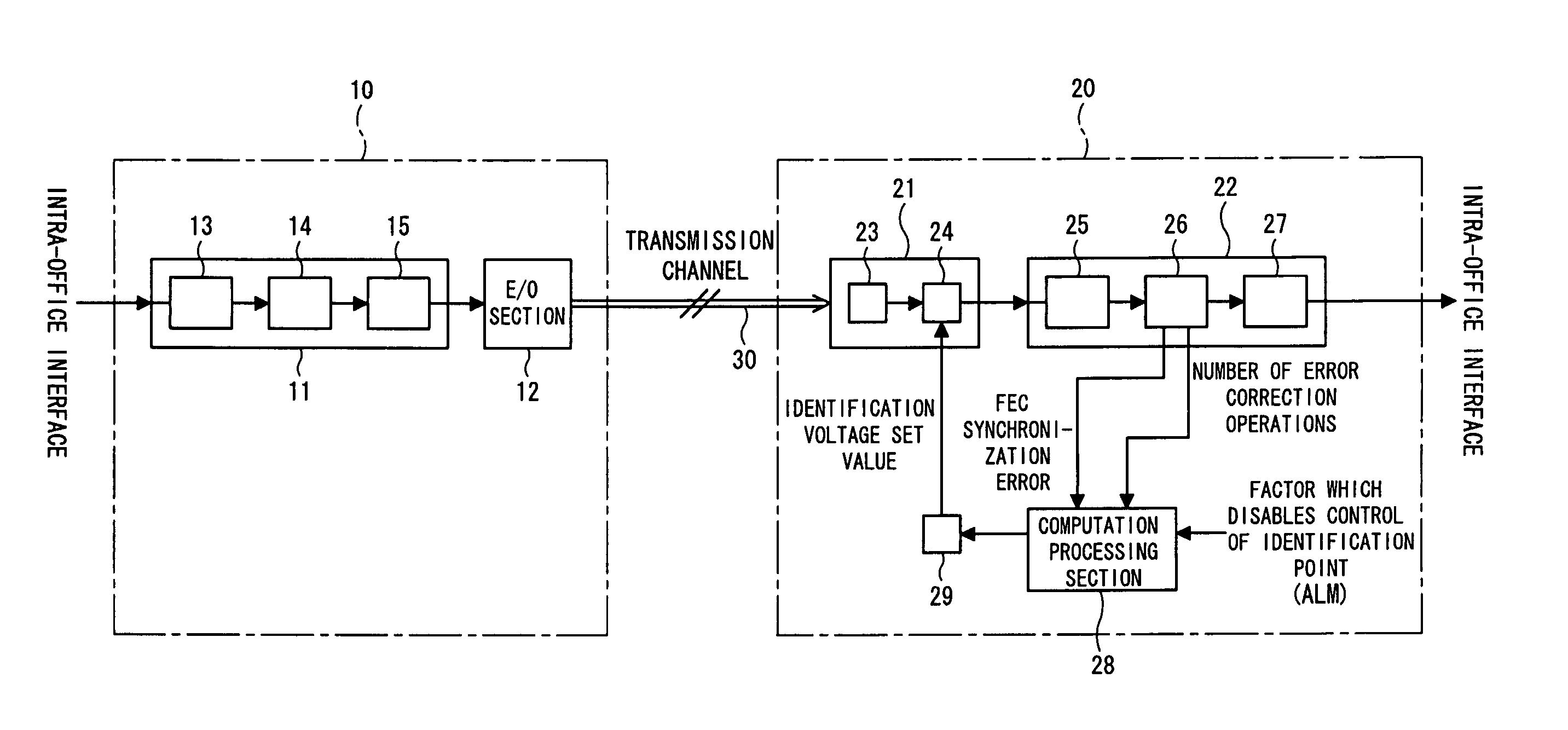
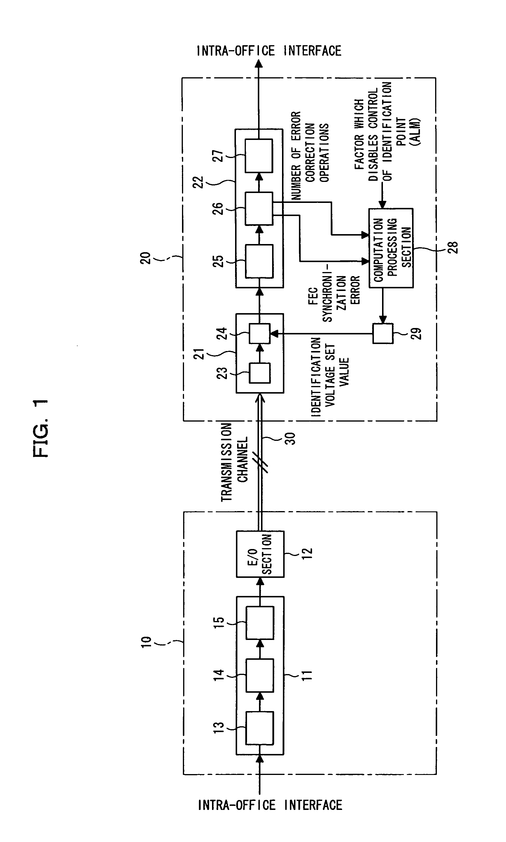
[0054]FIG. 1 is a block diagram showing an optical transmission system 1 according to an embodiment of the present invention. The optical transmission system 1 shown in FIG. 1 focuses attention on, particularly, improved exchange of an optical signal between a transmission converter and a receiving converter, which corresponds exchange of an optical signal between a transmission converter 101-1 to 101-n and a receiving converter 109-1 to 109-n shown in FIG. 7. Namely, the optical transmission system 1 shown in FIG. 1 is configured to transmit an optical signal formed by modulating data with light of specific wavelength by the transmission converter 10, and receive it in the receiving converter 20, and the receiving converter 20 outputs the received optical signal as a demodulated data signal.

[0055]In connection with the optical transmission system 1 shown in FIG. 1, the amplifiers...


PUM


Abstract

A method for controlling an identification point for binarization processing in an optical signal receiver which can diminish a code error rate by optimally tracking an identification point at all times in accordance with a received signal, thereby maintaining transmission quality high. The method comprises identification point electrical signal increment / decrement steps. When the number of error correction operations is determined to have reached a target value in a target value arrival determination step, an identification point electrical signal is left unchanged. In contrast, when the number of error correction operations is determined not to have reached the target value, the identification point electrical signal is incremented or decremented within a predetermined increment / decrement range such that the number of error correction operations approaches the target value.

Description

[0001]This application is a continuation application, filed under 35 USC 111(a), of International Application PCT / JP2003 / 007013, filed Jun. 3, 2003.FIELD OF THE INVENTION[0002]The present invention relates to an optical signal receiver and a method for controlling an identification point for binarization processing performed thereby. Particularly, the present invention relates to an optical signal receiver which can optimally determine an identification point regardless of an eye pattern and can optimally determine an identification point without mixing an error in transmission data during an in-service period, as well as to a method for controlling an identification point for binarization processing performed by the optical signal receiver.[0003]An optical transmission system starting with a submarine optical relay transmission system is in currently seeing increases in transmission capacity and transmission distance. A wavelength-multiplexed transmission system which multiplexes a...

Claims


Application Information

Patent Timeline
Patent Type & Authority Patents(United States)
IPC IPC(8): H04B10/06H04B10/08H04B17/00H04B10/07H04B10/40H04B10/50H04B10/556H04B10/60H04B10/69H04L1/00
CPCH04B10/695H04L1/203H04L25/063H04L1/0047
Inventor FUKUMITSU, KATSUMI
Owner FUJITSU LTD
Learn More