Method and system for communicating a clock signal over an optical link

a clock signal and optical link technology, applied in the field of optical communication systems, can solve problems such as cost-effectiveness, and achieve the effect of reducing or eliminating problems and disadvantages

Inactive Publication Date: 2005-09-06
FUJITSU LTD
View PDF21 Cites 47 Cited by
  • Summary
  • Abstract
  • Description
  • Claims
  • Application Information

AI Technical Summary

Benefits of technology

[0006]The present invention provides a method and system for communicating a clock signal over an optical link that substantially reduces or eliminated problems and disadvantages associated with prev...

Problems solved by technology

FEC typically requires good clock extraction which is difficult with very poor waveforms and/or a large amount of jitter present i...

Method used


Image

  • Method and system for communicating a clock signal over an optical link
  • Method and system for communicating a clock signal over an optical link
  • Method and system for communicating a clock signal over an optical link

Examples


Embodiment Construction

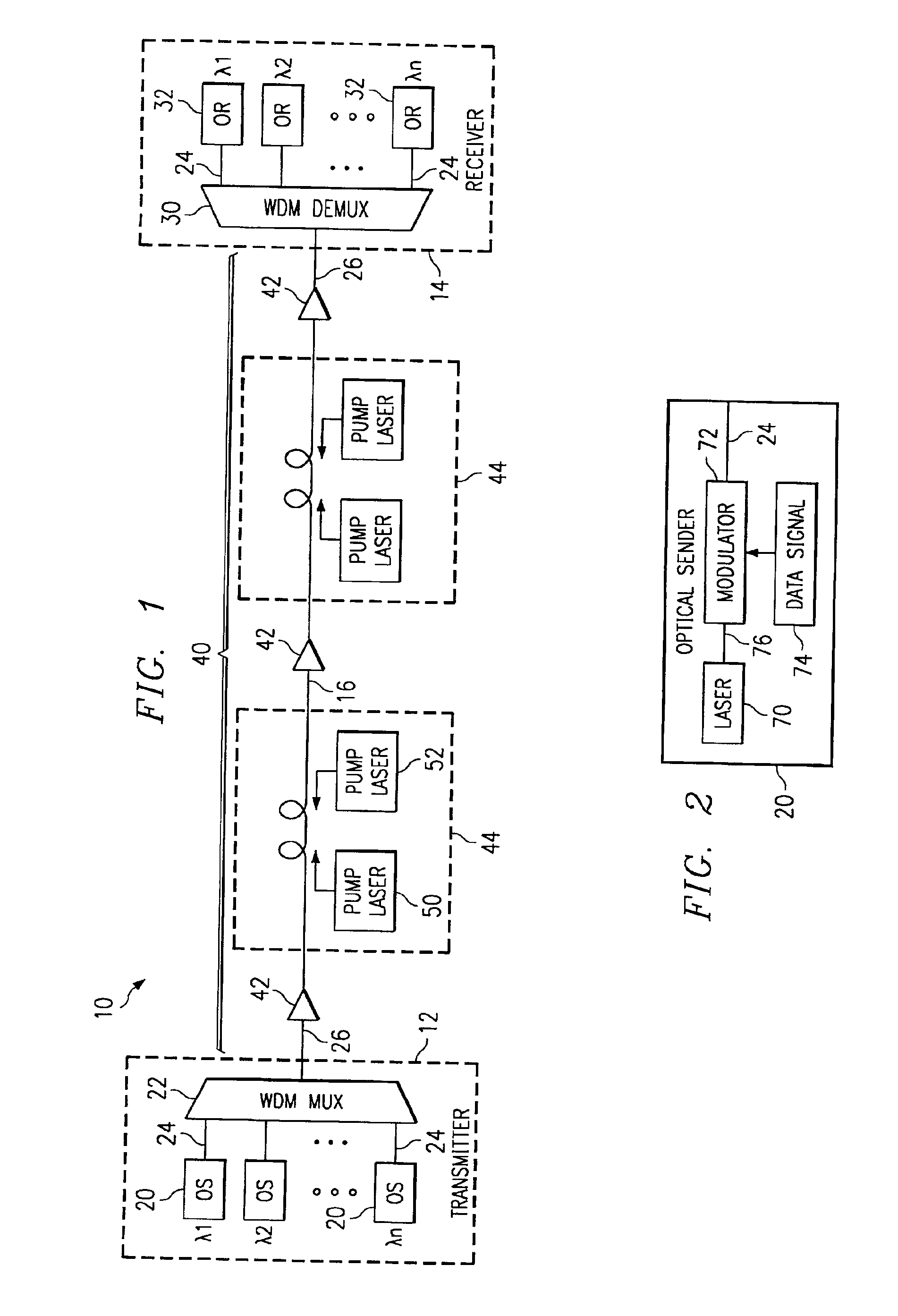
[0027]FIG. 1 illustrates an optical communication system 10 in accordance with one embodiment of the present invention. In this embodiment, the optical communication system 10 is a wavelength division multiplexed (WDM) system in which a number of optical channels are carried over a common path at disparate wavelengths. It will be understood that the optical communication system 10 may comprise other suitable single channel, multichannel or bi-directional transmission systems.

[0028]Referring to FIG. 1, the WDM system 10 includes a WDM transmitter 12 at a source end point and a WDM receiver 14 at a destination end point coupled together by an optical link 16. The WDM transmitter 12 transmits data in a plurality of optical signals, or channels, over the optical link 16 to the remotely located WDM receiver 14. Spacing between the channels is selected to avoid or minimize cross talk between adjacent channels. In one embodiment, as described in more detail below, minimum channel spacing (...


PUM


Abstract

A method and system for communicating a clock signal over an optical link includes receiving a multimodulated optical information signal including non-intensity modulation for a data signal and intensity modulation for a clock signal. The clock signal is recovered based on the intensity modulation of the multimodulated optical information signal. The non-intensity modulation for the data signal is converted to intensity modulation for the data signal. The data signal is recovered from the intensity modulation for the data signal using the clock signal.

Description

RELATED PATENT APPLICATIONS[0001]This application is related to U.S. patent application Ser. No. 09 / 853,323 entitled “Method and System for Transmitting Information in an Optical Communication System Using Distributed Amplification,” U.S. patent application Ser. No. 09 / 853,318 entitled “Receiver and Method for a Multichannel Optical Communication System,” U.S. patent application Ser. No. 09 / 853,316 entitled “Method and System for Demultiplexing Non-Intensity Modulated Wavelength Division Multiplexed (WDM) Signals,” and U.S. patent application Ser. No. 09 / 853,340 entitled “Method and System for Tuning an Optical Signal Based on Transmission Conditions,” all filed on May 10, 2001.TECHNICAL FIELD OF THE INVENTION[0002]The present invention relates generally to optical communication systems, and more particularly to a method and system for communicating a clock signal over a optical link.BACKGROUND OF THE INVENTION[0003]Telecommunications systems, cable television systems and data commu...

Claims


Application Information

Patent Timeline
IPC IPC(8): H04B10/17H04B10/155H04B10/152H04B10/12H04L7/00H04B10/00H04B10/04H04J1/00H04B10/06H04B10/142H04J14/08
CPCH04B10/5051H04L7/0075H04B10/2503H04B10/506H04B10/2589
Inventor ONAKA, HIROSHI
Owner FUJITSU LTD
Why Eureka
Try Eureka