High data rate interconnecting device

a technology of interconnection device and high data rate, which is applied in the direction of cross-talk reduction, line-transmission details, coupling device connection, etc., can solve the problems of increasing reflected energy, data signals become distorted and attenuated, and increase the rate of data signals, so as to minimize the effect of three kinds of interference parasitic effects, and reducing the number of interferences

Inactive Publication Date: 2008-01-01
RIT TECHNOLOGIES
View PDF6 Cites 282 Cited by
  • Summary
  • Abstract
  • Description
  • Claims
  • Application Information

AI Technical Summary

Benefits of technology

[0013]It is still another object of the present invention to provide an interconnecting device that allows minimizing impedance mismatches, caused by said low frequency switch.
[0032]Differential transmission lines can be maintained balanced as they are fabricated while ensuring that a first conductive strip line of each transmission line passes essentially above, and overlaps, the corresponding second conductive strip line of the same transmission line. By overlapping strip lines of same transmission line, an effect similar to the effect of ‘twisted-pair’ cable is achieved, namely, a considerable immunity to external interference is achieved.

Problems solved by technology

A major problem exists whenever a high-rate data signal is forwarded through a (physical) channel.
The problem with physical channels originally designed for relatively low rate data signals, is that at higher data rates (i.e., at higher frequencies) the data signals become distorted and attenuated due to energy losses and parasitic effects.
This problem becomes acute whenever the physical channel includes an interconnecting device for interconnecting between two data devices.
This phenomenon is due to impedance mismatches between the devices and cross-talk interference between their corresponding transmission lines, resulting, e.g., in increased reflected energy (i.e. energy losses) and deterioration in the quality of data signals.
In case when the communication path comprises differential transmission line, the balance of the differential lines is also deteriorated due to these parasitic effects.
However, attempts have been made to use switches as interconnecting devices in frequency bandwidth higher than 100 MHz, which resulted in sever deterioration in the data signal passing through such switches within this bandwidth.
Switch 14, on the other hand, has introduced significant parasitic elements that caused impedance mismatches, mutual interference between adjacent transmission lines (i.e. cross talk) and transmission lines were taken out of balance.
All of the methods described above have not yet provided satisfactory solutions to the problem of utilizing a switch, whether as a sole device or in combination with a cord-based interconnecting device, for forwarding high-rate data signals.

Method used


Image

  • High data rate interconnecting device
  • High data rate interconnecting device
  • High data rate interconnecting device

Examples


Embodiment Construction

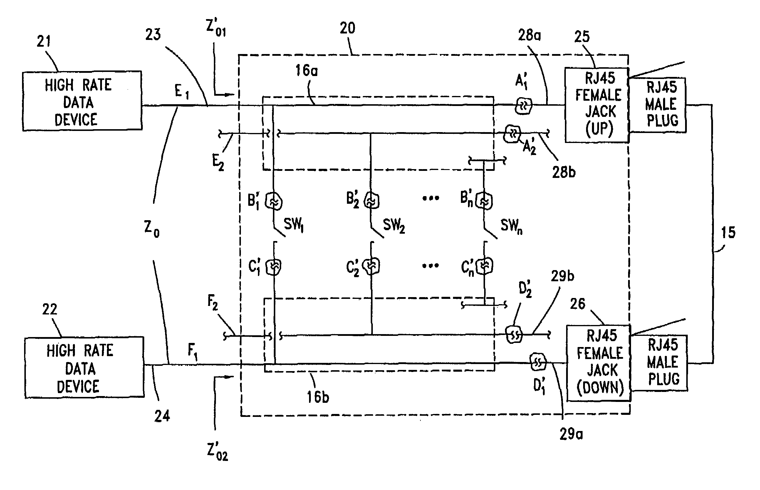
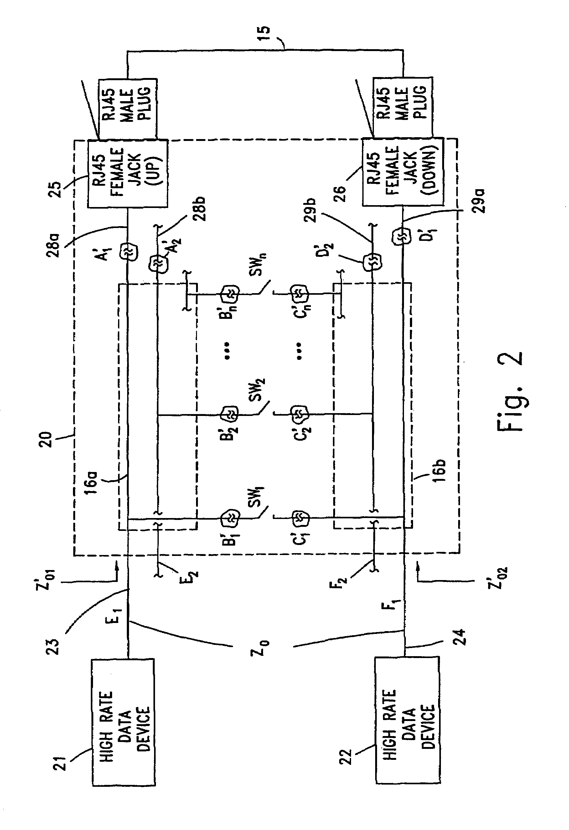
[0045]FIG. 2 illustrates the utilization of the prior art interconnect module illustrated in FIG. 1, for connecting two high-rate data systems 21 and 22. Assuming a high-rate data flow from server 21 to user 22, an optimal case would be having transmission line 23 impedance equal to the impedance of interconnecting module 13, i.e. ZO=ZO1 (FIG. 1), in which case no compensation arrangements A′i, B′i, C′i and D′i (FIG. 2) would be required. However, as described before, interconnecting module 13 (FIG. 1) introduces impedance that significantly differs from ZO (i.e. ZO1O) whenever high-rate data signals are involved. This impedance mismatch is frequency dependent and becomes more acute as the frequency of the forwarded data signal becomes higher, due to growing energy reflections caused by ‘improper’ (i.e., deviating from the characteristic value) impedance introduced by interconnecting module 13 (FIG. 1). Consequently, the signal becomes more distorted and attenuated as it propagates ...


PUM


Abstract

An interconnect apparatus for providing a communication path for data signals in a predetermined frequency band, that includes a first and a second sections of a transmission line, connected at one end to first and second data transceiving devices, respectively. A switch, such as a mechanical, electro-mechanical, electronic, electro-magnetic and electro-optical switch, having conductive / non-conductive states, is provided for connecting / disconnecting between the other ends of the first and the second sections, for providing a data communication path between the data transceiving devices while being in its conductive state a third and a fourth sections of a transmission line, each of which connected at one end to a contact of the switch and at the other end to a first and a second connector, respectively. A compensation circuitry is provided for compensating, within the frequency band, parasitic effects caused by the switch and / or cord, while the switch is in its conductive state or, while the switch is in its non-conductive state and while a connection between the first and the second connectors is provided by a cord having predetermined characteristics, such that the compensation circuitry compensates the influence of parasitic effects introduced along the communication path by the switch while being in its non-conductive state and while the cord is a part of the communication path or, by the combination of the third and a fourth sections and the connectors while the switch is in its conductive state.

Description

RELATED APPLICATION[0001]This application is a Continuation Application of PCT International Application No. PCT / IL02 / 00697, filed Aug. 22, 2002, entitled “HIGH DATA RATE INTERCONNECTING DEVICE”, which in turn claims priority from Israeli Patent Application No. 145103, filed Aug. 23, 2001, entitled “HIGH DATA RATE INTERCONNECTING DEVICE”, both of which are incorporated by reference herein in their entirety.BACKGROUND OF THE INVENTION[0002]1. Field of the Invention[0003]The present invention relates to the field of interconnecting devices for data communication. More particularly, the invention relates to an interconnecting device being a part of a communication path, for allowing the transmission of high rate data signals over the communication path.[0004]2. Prior Art[0005]The number of devices and systems capable of exchanging high-rate digital data (i.e. wideband signals) is growing rapidly. Such systems are, for example, computers / LAN and WAN networks, telecommunication systems a...

Claims


Application Information

Patent Timeline
Patent Type & Authority Patents(United States)
IPC IPC(8): H01P1/10H01P1/04H01R24/00H01R13/6466H01R13/6474H01R13/719H04B3/32H05K1/02
CPCH05K1/0228H01R13/6474H01R13/6466H01R2201/04H05K2201/10053H05K2201/10189H01R13/719
Inventor GUROVICH, DMITRYHAGGAY, YAAKOV
Owner RIT TECHNOLOGIES
Why Eureka
Try Eureka