Wireless communications including an antenna for wireless power transmission and data communication and associated methods

a technology of wireless power transmission and data communication, applied in the field of wireless communication, can solve the problems of not being able to provide radio frequency (rf) power and communication link simultaneously

Active Publication Date: 2010-08-26
HARRIS CORP
View PDF9 Cites 274 Cited by
  • Summary
  • Abstract
  • Description
  • Claims
  • Application Information

AI Technical Summary

Problems solved by technology

Although various antennas are known for power transmission and communication they do not include isolated ports and cannot simultaneously provide the radio frequency (RF) power and communications link, e.g. diversity in the field of wireless RF identification (RFID) tags.

Method used


Image

  • Wireless communications including an antenna for wireless power transmission and data communication and associated methods
  • Wireless communications including an antenna for wireless power transmission and data communication and associated methods
  • Wireless communications including an antenna for wireless power transmission and data communication and associated methods

Examples


Embodiment Construction

[0026]The present invention will now be described more fully hereinafter with reference to the accompanying drawings, in which preferred embodiments of the invention are shown. This invention may, however, be embodied in many different forms and should not be construed as limited to the embodiments set forth herein. Rather, these embodiments are provided so that this disclosure will be thorough and complete, and will fully convey the scope of the invention to those skilled in the art. Like numbers refer to like elements throughout.

[0027]As discussed above, features of the present invention may apply to the field of radio frequency identification (RFID). RFID tags may be defined in three general types: passive, active, or semi-passive (also known as battery-assisted). Passive tags require no internal power source, thus being pure passive devices (they are only active when a reader is nearby to power them). Semi-passive and active tags use a power source, usually a small battery. To c...


PUM


Abstract

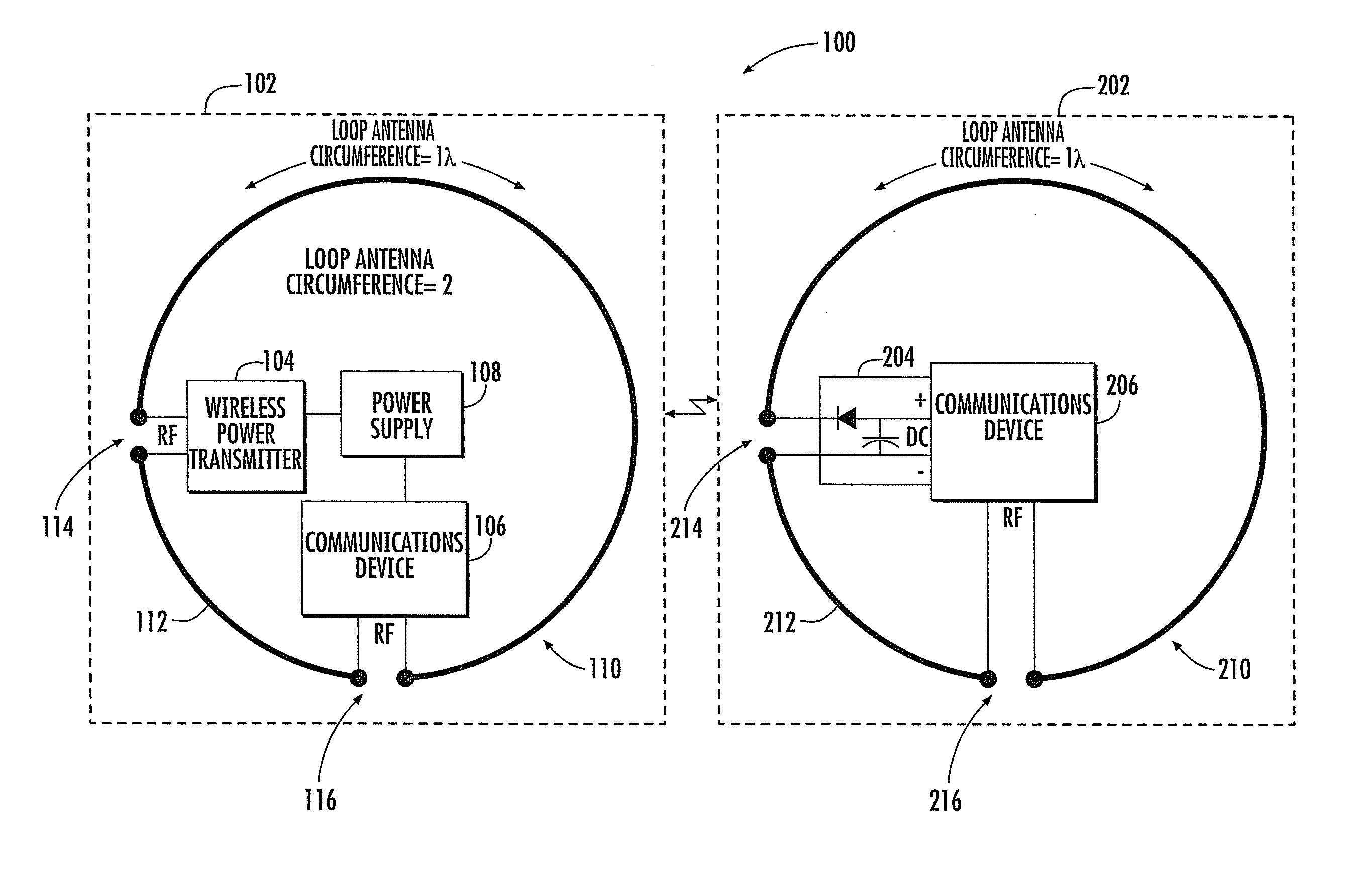
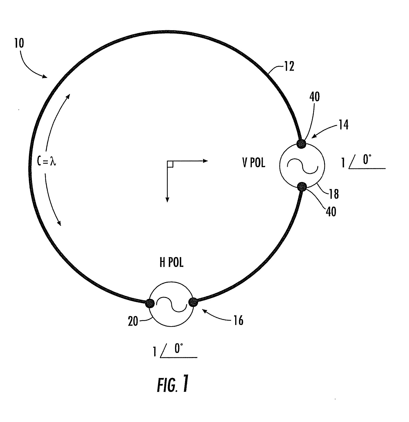
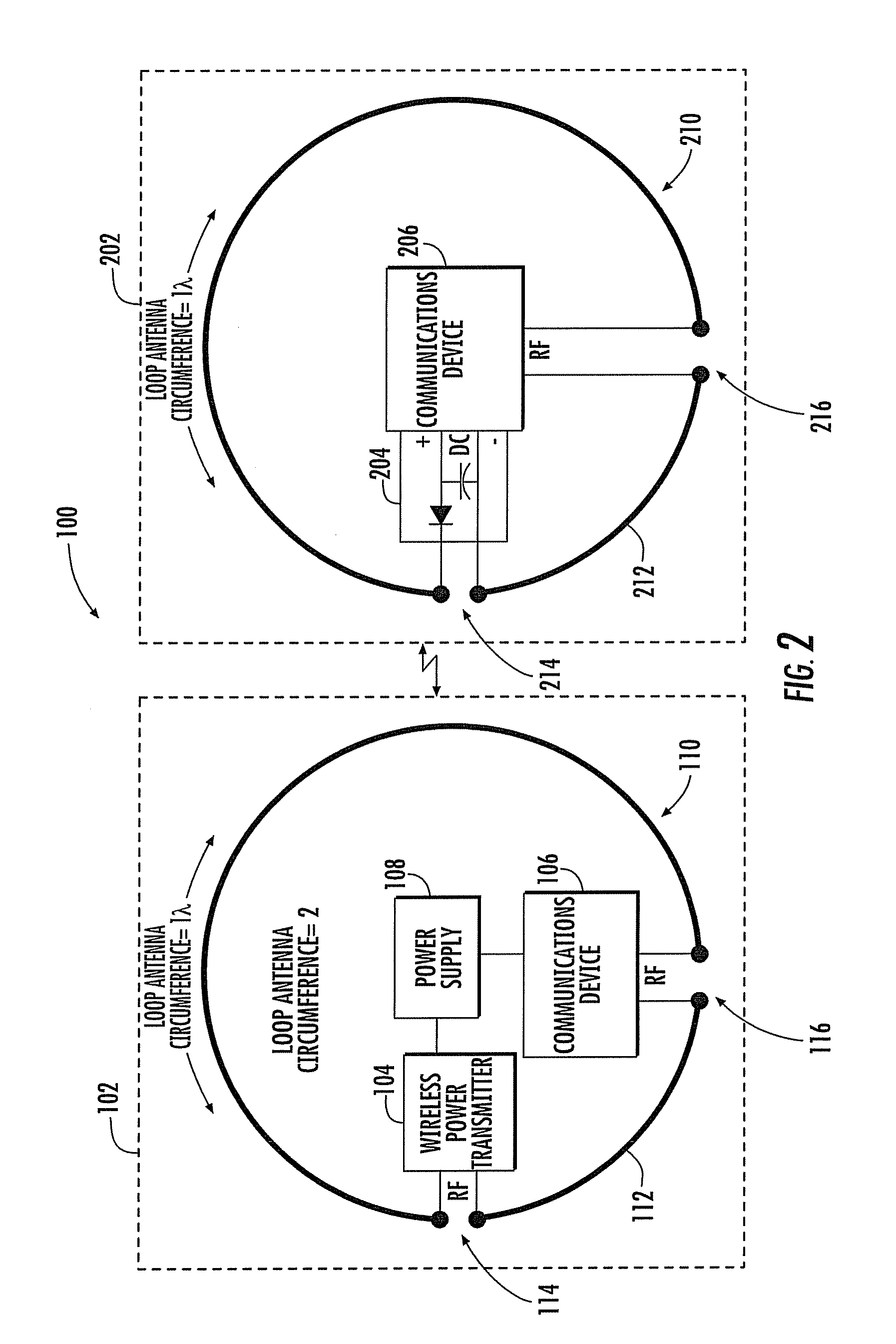
The wireless communication system includes a first device, e.g. a radio frequency identification (RFID) reader, having a wireless power transmitter, a first wireless data communications unit, and a first dual polarized loop antenna having isolated signal feedpoints along a first loop electrical conductor. The wireless power transmitter transmits a power signal having a first polarization, and the first wireless data communications unit communicates using a data signal having a second polarization. A second device, e.g. an RFID tag, includes a second dual polarized loop antenna. A second wireless data communications unit communicates with the first wireless data communications unit of the first device using the data signal having the second polarization. A wireless power receiver receives the power signal having the first polarization from the wireless power transmitter of the first device, and provides power for the second device.

Description

FIELD OF THE INVENTION[0001]The present invention relates to the field of communications, and, more particularly, to antennas for wireless communication and related methods.BACKGROUND OF THE INVENTION[0002]Power requirements for modern, solid state electronics are progressively becoming lower and lower. For example, the Liquid Crystal Display (LCD) may require only milliwatts for operation, and the field effect transistor (FET) can respond to even small static charges. This has enhanced the utility of wireless power transmission as an approach for energizing electronics. An example and application of wireless power for electronics is the Radio Frequency Identification (RFID) transponder “tag”, which can allow a method of storing and remotely retrieving data to a reader.[0003]As background, wireless power transmission can be the conveyance of electrical energy by radio frequency (RF) techniques, such as the electric power transmitted and received between two radio antennas. Depending...

Claims


Application Information

Patent Timeline
Patent Type & Authority Applications(United States)
IPC IPC(8): H01Q11/12H01Q1/24H02J11/00
CPCH01Q7/00H01Q1/2208G06K19/0708H02J50/80
Inventor PARSCHE, FRANCIS EUGENE
Owner HARRIS CORP
Why Eureka
Try Eureka