Radiotelecontrol intelligent light control system capable of setting control light hint map

A technology of radio remote control and intelligent lighting, applied in electric light source, signal transmission system, energy-saving control technology, etc., can solve the problems of easy overlapping of passwords, inconvenient use, and no control.

Inactive Publication Date: 2008-12-24
李舒
View PDF5 Cites 46 Cited by
  • Summary
  • Abstract
  • Description
  • Claims
  • Application Information

AI Technical Summary

Problems solved by technology

[0002] With the development of science and technology and the improvement of people's quality of life, at present, the light control switch fixedly installed on the wall can no longer meet people's requirements for its use, and the electronic products of infrared remote control light make it used in a certain range of applications , but because of the directionality of remote control in infrared remote control, it also cannot satisfy people's pursuit of high-quality high-tech life. Although electronic products with radio remote control overcome the directionality of use, they have no directionality of control, so In use, a password must be set to overcome the mutual control of use, and the password setting method currently used is to use a three-state method to set the password chip (such as PT2262 and PT2272), and the password setting needs to be set by hardware one by one, so use It is very inconvenient to get up, and the obtained passwords are easy to overlap. Although radio remote control is more convenient than infrared remote control, the electronic products with radio remote control now have numbers such as 1, 2, and 3 on the keys on the remote control (hereinafter referred to as the transmitter), and 1 , Numbers 2 and 3 correspond to remote control rooms 1, 2 and 3, but only the homeowner knows which room is controlled by the number key. If a guest comes, you have to ask, so it is inconvenient to use
[0003] The above-mentioned control of the lights can only be controlled by the switch of the lights. In the application of smart home control and the promotion and application of energy-saving products, it is obvious that the above-mentioned products can no longer be widely used.

Method used


Image

  • Radiotelecontrol intelligent light control system capable of setting control light hint map
  • Radiotelecontrol intelligent light control system capable of setting control light hint map
  • Radiotelecontrol intelligent light control system capable of setting control light hint map

Examples


Embodiment Construction

[0091] The present invention will be further described below in conjunction with the accompanying drawings and specific embodiments.

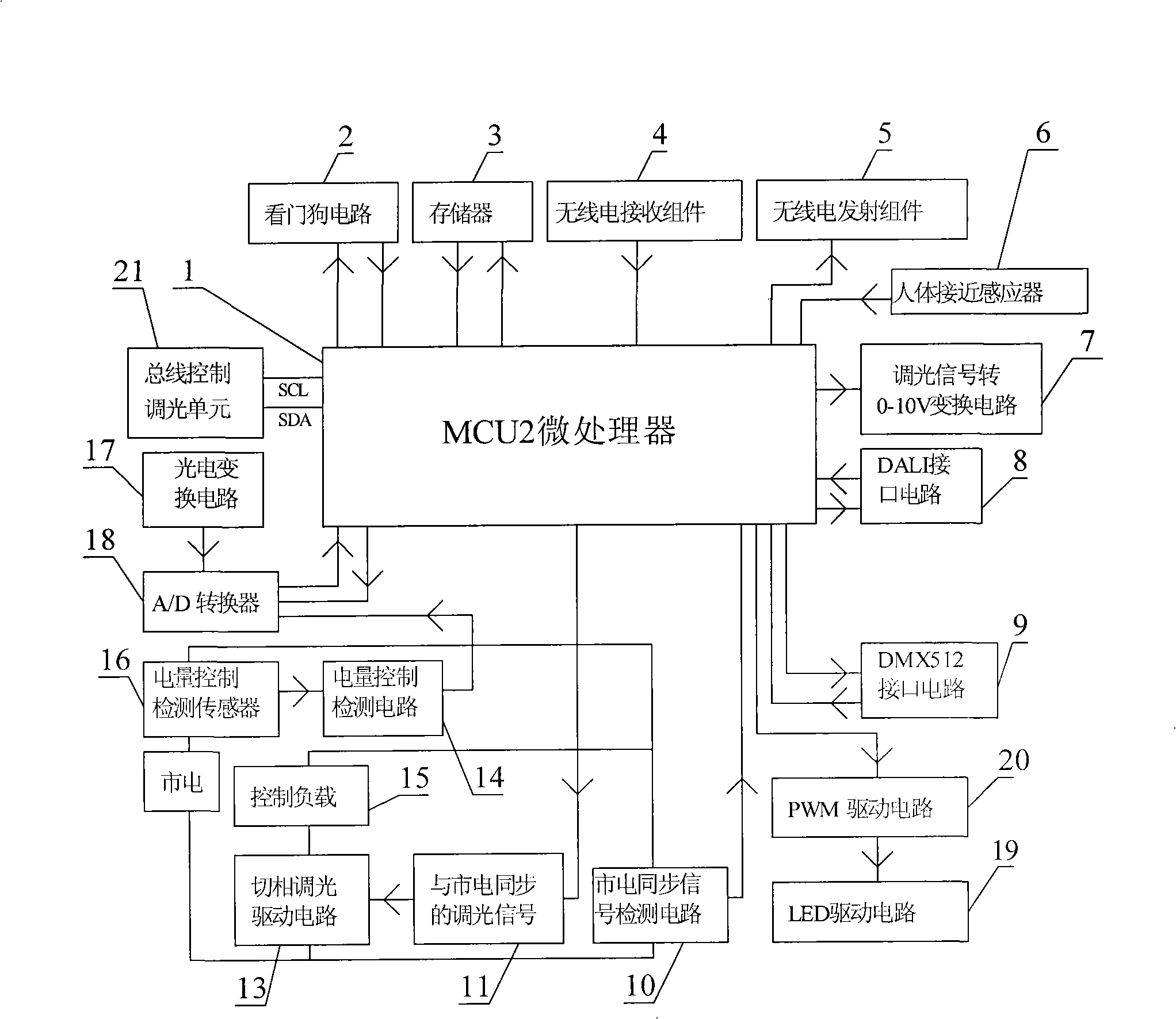
[0092] Such as figure 1 Shown is the functional block diagram of the receiver hardware of the present invention.

[0093] The hardware of the receiver includes: MCU2 microprocessor (1), watchdog circuit (2), memory (3), radio receiving assembly (4), radio transmitting assembly (5), human body proximity sensor (6) , dimming signal to 0-10V voltage conversion circuit (7), DALI interface circuit (8), DMX512 interface circuit (9), mains synchronous signal detection circuit (10), phase-cut dimming drive circuit (13), power Control detection circuit (14), power control detection sensor (16), photoelectric conversion circuit (17), A / D converter (18), LED drive circuit (19), PWM drive circuit (20), bus control dimming unit (twenty one).

[0094] The hardware connection relationship of the receiver is:

[0095] The watchdog circuit (2), memory (3), ...


PUM


Abstract

The invention discloses a radio remote-controlled intelligent light control system which can be provided with light controlling diagrammatic maps, and comprises a microprocessor, a memory, a radio receiving and transmitting assembly, a touch-screen LCD, a key, an optical inductor and system processing software. The same address of a transmitter and a receiver, as well as the self serial number of a lamp are set, so as to ensure that the transmitter and the receiver are established to form a multi-unit communication system; therefore, the radio remote control of the light or electric apparatus can be realized; the touch-screen LCD on the transmitter displays control results and the light position control diagrammatic maps. The light control system is suitable for use in households, hotels and restaurants, companies, etc.

Description

Technical field [0001] The invention relates to a radio remote control, in particular to an intelligent lighting control system in which a radio remote control can be set to control a schematic map of lighting. Background technique [0002] With the development of science and technology and the improvement of people's quality of life, at present, the light control switch fixedly installed on the wall can no longer meet people's requirements for its use, and the electronic products of infrared remote control light make it used in a certain range of applications , but because of the directionality of remote control in infrared remote control, it also cannot satisfy people's pursuit of high-quality high-tech life. Although electronic products with radio remote control overcome the directionality of use, they have no directionality of control, so In use, a password must be set to overcome the mutual control of use, and the password setting method currently used is to use a three...

Claims


Application Information

Patent Timeline
Patent Type & Authority Applications(China)
IPC IPC(8): H05B37/02G08C17/02
CPCY02B20/40
Inventor 李舒
Owner 李舒
Why Eureka
Try Eureka