
Radio remote address programmable two-way communication digital light control system

A technology of radio remote control and two-way communication, applied in electrical program control, signal transmission system, electric light source, etc., can solve problems such as waste of users, lack of promotion, and difficulty in modification

Inactive Publication Date: 2011-05-11
李舒
View PDF4 Cites 3 Cited by
  • Summary
  • Abstract
  • Description
  • Claims
  • Application Information

AI Technical Summary

Problems solved by technology

This password setting method, once the password is set, it is not easy for users who do not have professional tools to modify it. If one of the receiver or the transmitter is broken, both of them have to be scrapped (now There are such products in the market), which is a waste for users, so they cannot be promoted
Moreover, this point-to-point control method, when the receiver receives a valid signal, the receiver emits a sound or uses a light indicator to notify the received signal, so the remote control can only be used for remote control that is relatively close or within the range that people can perceive , if the remote control is far away or next door, it is difficult to know the result of the remote control

Method used


Image

  • Radio remote address programmable two-way communication digital light control system
  • Radio remote address programmable two-way communication digital light control system
  • Radio remote address programmable two-way communication digital light control system

Examples


Embodiment Construction

[0071] The present invention will be further described below in conjunction with the accompanying drawings and specific embodiments.

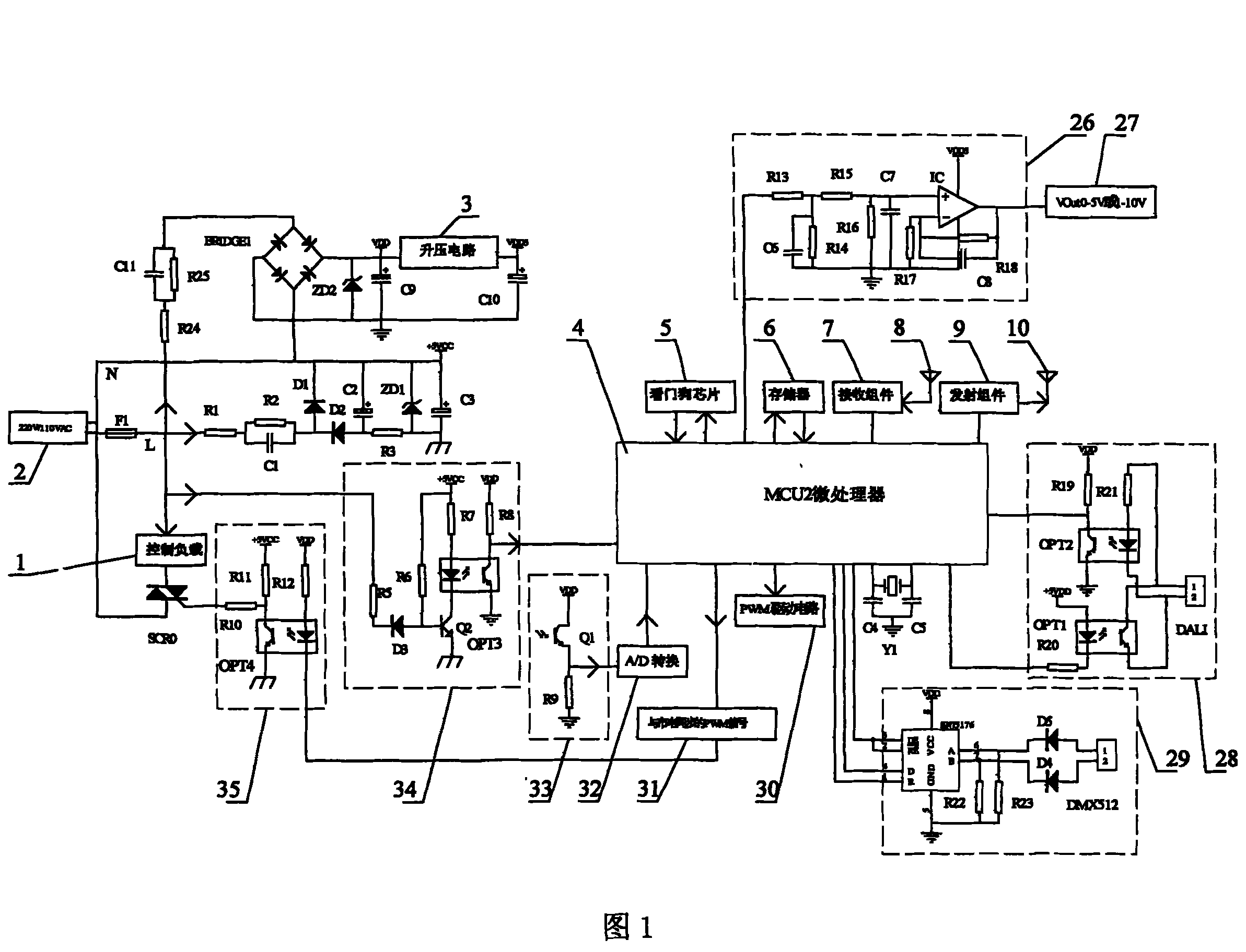
[0072] As shown in FIG. 1 , it is a schematic diagram of the receiver circuit of the present invention. Including A / D conversion circuit (32), control load (1), PWM driving circuit (30), microprocessor MCU2 (4), watchdog chip (5), memory (6), receiving component (7), Transmitting component (9), 0-5V or 1-10V output (27), boost circuit (3), PWM signal output (31) synchronous with mains power, radio receiving antenna (8), radio transmitting antenna (10) , mains synchronous signal detection circuit (34), DMX512 interface circuit (29), DALI interface circuit (28), PWM voltage conversion circuit (26), light sensor (33), thyristor drive circuit (35).

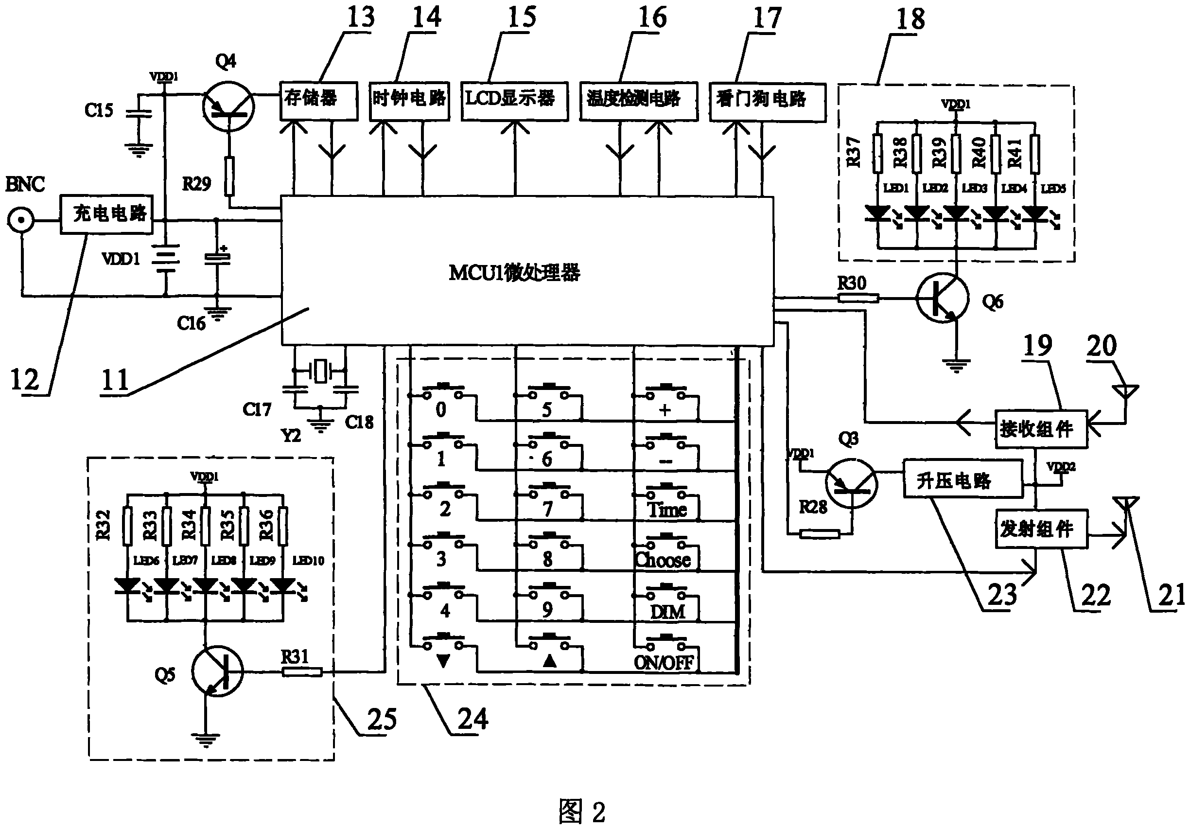
[0073] As shown in FIG. 2 , it is a schematic diagram of the transmitter circuit of the present invention. Including microprocessor MCU1 (11), charging circuit (12), EEPROM memory (13), clock circuit...


PUM


Abstract

The invention relates to a radio remote control address programmable and bi-directional communication digital light control system, comprising a micro processor, a memory, a radio sending and receiving module, a LCD display, a plurality of keys, a photo inductor, a communication interface circuit for DMX512 and DALI and a plurality of system processing software. The invention has the advantages that the functions of on, off, timing and light-adjusting for the a wireless remote control light or a wireless remote control electric appliance are realized; a programmable online radio for user address setup is provided; the emitter can control the receiver as long as the emitter has the same address as the receiver; the communication is bi-directional while the control is unidirectional; the LCD of the emitter displays human-machine conversation and integrates the functions of time, temperature, timing and switch. The invention is suitable for the control and use of radio remote control light and household appliances in families, hotels, restaurants, companies and other locations.

Description

Technical field [0001] The invention relates to a radio remote control system, in particular to a radio remote control address programmable two-way communication digital lighting control system. Background technique [0002] At present, the switch control of the light generally adopts a mechanical switch, which is fixedly installed on the wall, and its on or off state is controlled by pulling or pressing. The dimming of the light is composed of potentiometers, thyristors and other components, and the conduction angle of the thyristors is adjusted by rotating the potentiometers for dimming. There are also some dimmers with analog voltage 1-10V or 0-5V interface, and the dimming can be realized by adjusting the potentiometer to adjust the voltage. Products with wireless remote control and programmable timing to control lighting are rare. In the field of radio remote control, the common means of radio remote control are generally two kinds of infrared rays and radio. In the ...

Claims


Application Information

Patent Timeline
Patent Type & Authority Patents(China)
IPC IPC(8): H05B37/02G08C17/02G05B19/02
CPCY02B20/40
Inventor 李舒
Owner 李舒
Learn More