Karabiner with locking ring

a locking ring and karabiner technology, applied in the field of karabiner, can solve the problems of long opening sequence, complicated handling of karabiner, tedious screw tightening operation, etc., and achieve the effect of improving handling

Inactive Publication Date: 2008-01-22
ZEDEL CORP
View PDF10 Cites 41 Cited by
  • Summary
  • Abstract
  • Description
  • Claims
  • Application Information

AI Technical Summary

Benefits of technology

[0010]The object of the invention consists in providing a safety karabiner with positive locking of the gate enabling handling to be improved.
[0012]Manual unlocking of the lock-bolt and actuation of the ring in translation to the unlocked position are performed quickly by a single action of the climber.

Problems solved by technology

This screw-tightening operation is tedious and takes a relatively long time to perform.
The same drawback arises when unscrewing to make the ring go from the first locked position to the second unlocked position.
The second rotational movement to unlock the ring lengthens the opening sequence and complicates handling of the karabiner.
The device does not however have a lock performing positive locking of the ring.
Such a command complicates handling for fitting the ring.

Method used


Image

  • Karabiner with locking ring
  • Karabiner with locking ring
  • Karabiner with locking ring

Examples


Embodiment Construction

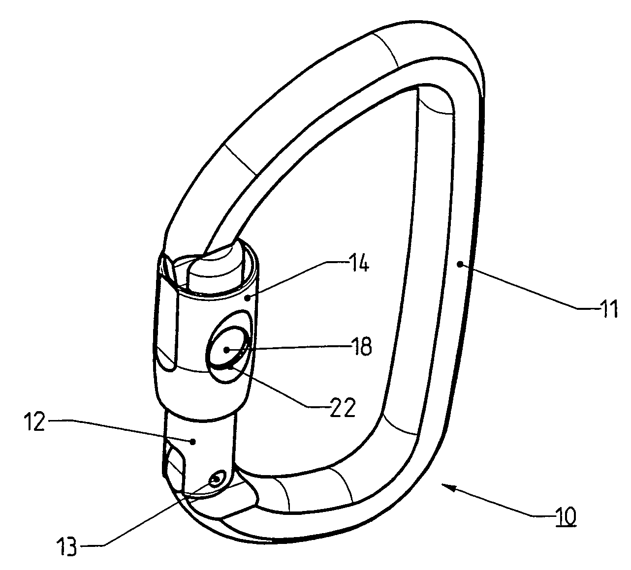
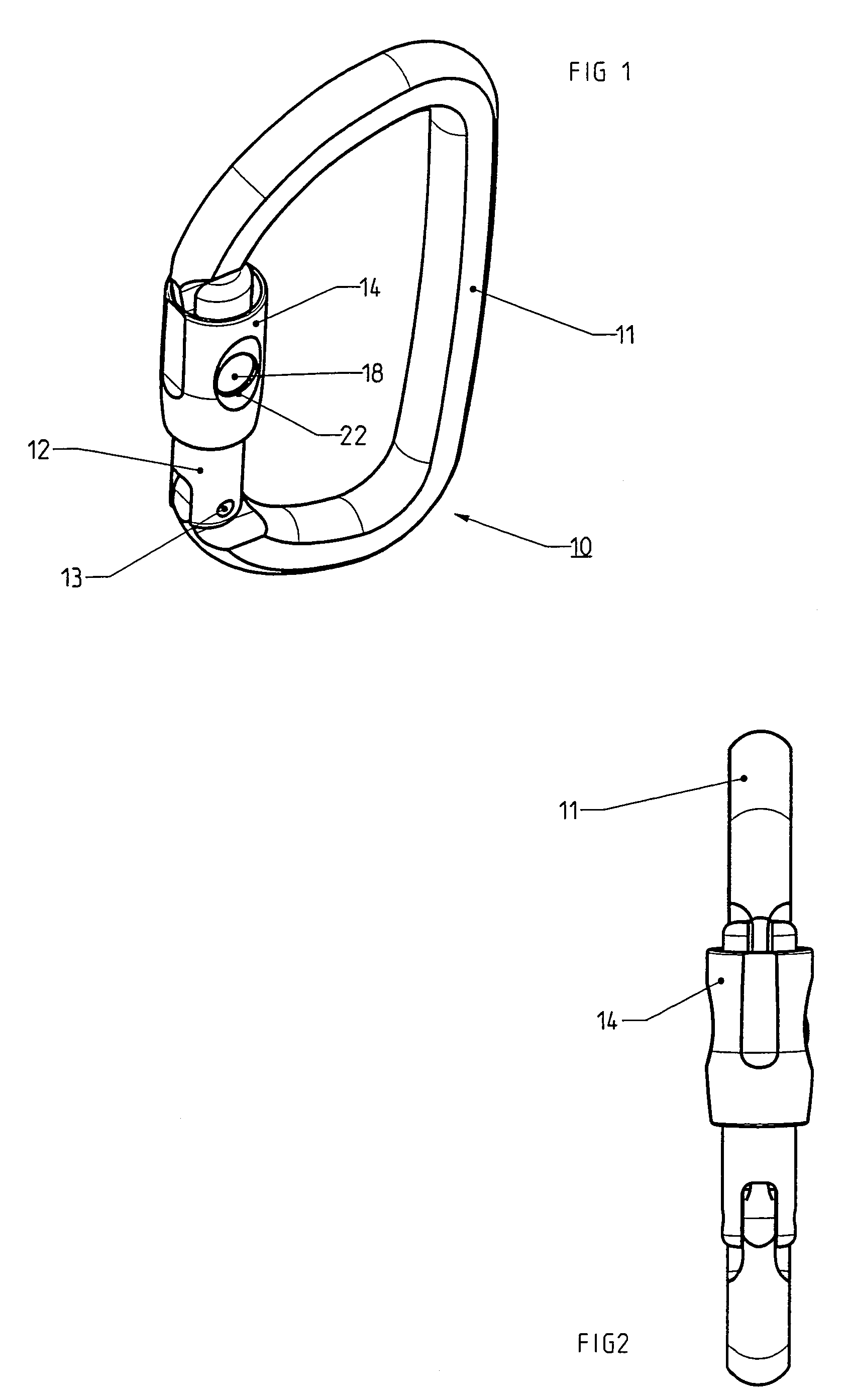
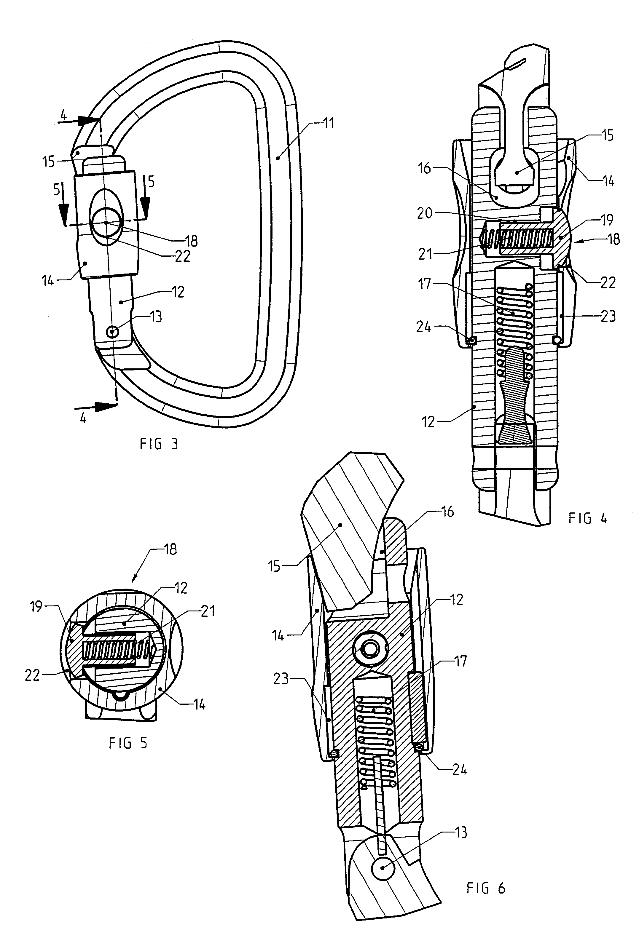
[0030]In the figures, a karabiner 10 for climbing and mountaineering comprises a C-shaped metal body 11 and a movable gate 12 mounted swivelling on a spindle 13 situated at the bottom end of the body 11. The movable gate 12 is equipped with a coaxial locking ring 14 slidingly mounted on the gate 12 between a first locked position (FIGS. 1 to 6) and a second unlocked position (FIGS. 7 to 13).

[0031]In the unlocked position of the ring 14, the gate 12 is able to be moved towards the inside of the body 11 allowing the karabiner to be opened (FIG. 12) to enable either a rope or a strap to be inserted or the karabiner to be hooked onto a securing device (not shown).

[0032]The top end of the body 11 is provided with a male securing part 15 able to engage in a female latching part 16 of the gate 12 when it is returned to the closed position (FIG. 7) by the action of a return spring 17. The male securing part 15 presents for example a reverse T-shaped structure comprising a tab extended by a ...


PUM


Abstract

A safety karabiner comprises a swivelling gate with a sliding locking ring operating in conjunction with a lock-bolt. The ring comprises a hole for receiving the lock-bolt at the end of the translation travel to the first locked position to constitute both a mechanical blocking device of the ring and a first visual indicator indicating the locked state. The lock-bolt is fitted on the movable gate.

Description

BACKGROUND OF THE INVENTION[0001]The invention relates to a karabiner comprising a fixed C-shaped body having a first end shaped as a securing part and a second end for articulation of a gate movable around a pivoting spindle between a closed position and an open position, said gate comprising:[0002]a latching part situated opposite the pivoting spindle to operate in conjunction with the securing part in the closed position,[0003]a return spring to return the gate to the closed position,[0004]a locking ring fitted coaxially around the gate and having a shorter length than that of the gate, said ring being movable between a first locked position blocking the gate in the closed position and a second unlocked position enabling the gate to be moved to the open position,[0005]and a lock-bolt able to block the ring positively in said first locked position.STATE OF THE ART[0006]Known karabiners equipped with locking rings of the kind referred to generally use screw-type or bayonet-type fas...

Claims


Application Information

Patent Timeline
Patent Type & Authority Patents(United States)
IPC IPC(8): F16B45/02F16B45/00
CPCF16B45/02Y10T24/45372Y10T24/4534Y10T24/45277F16B45/026F16B45/029F16B45/023
Inventor PETZL, PAULPLAZE, PIERRE
Owner ZEDEL CORP
Why Eureka
Try Eureka