Anastomosis instrument and method

Inactive Publication Date: 2008-01-29
UNITED STATES SURGICAL CORP
View PDF193 Cites 1272 Cited by
  • Summary
  • Abstract
  • Description
  • Claims
  • Application Information

AI Technical Summary

Problems solved by technology

However, such procedures that involve large incisions and substantial displacement of the rib cage are often traumatic to the patient with significant attendant risks.
The recovery period may be extensive and is often painful.
Furthermore, patients for whom coronary surgery is indicated may need to forego such surgery due to the risks involved with gaining access to the heart.
Such procedures require the introduction of multiple catheters into the blood vessels adjacent the heart, which is complicated procedure requiring that the desired vessels be properly located and accessed.
Furthermore, the introduction of catheters forms punctures in the blood vessels that must be subsequently closed, and there is an increased risk of trauma to the interior walls of the vesse

Method used


Image

  • Anastomosis instrument and method
  • Anastomosis instrument and method
  • Anastomosis instrument and method

Examples


Embodiment Construction

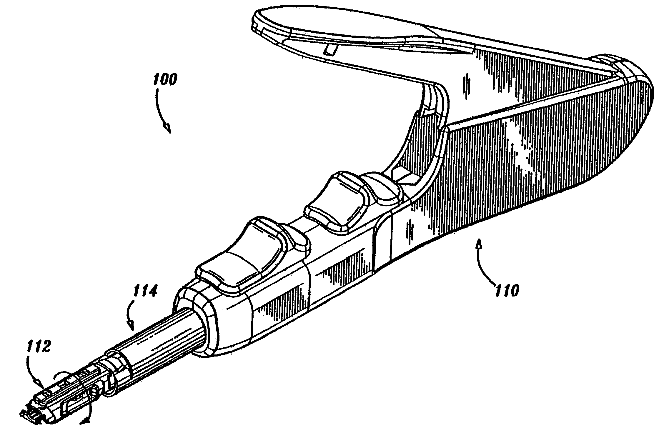
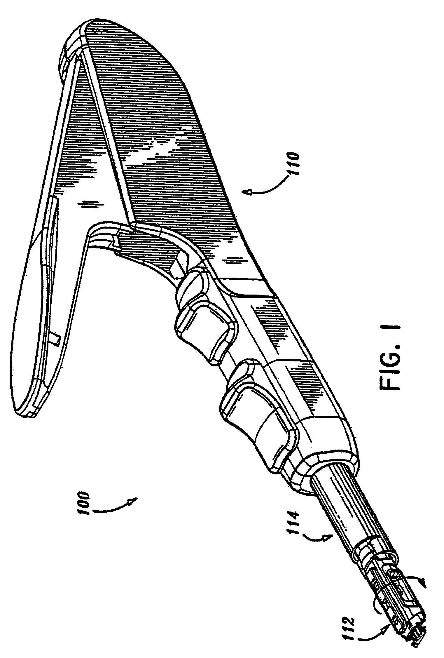
[0065]Preferred embodiments of the surgical instrument and method disclosed herein will be described in terms of a minimally invasive direct coronary artery bypass (MIDCAB) procedure wherein a vascular anastomosis is created by joining a section of a harvested vessel, e.g., the internal memory artery (IMA) to bypass an occlusion in a coronary artery, e.g., the left anterior descending artery (LAD). However, the presently disclosed surgical anastomosis instrument may also be utilized in performing anastomosis of other tubular luminal body structures. For example, the presently disclosed surgical anastomosis instrument may also be utilized to perform an A-V fistula to facilitate hemodialysis. This procedure consists of an end-to-side anastomosis joining an artery and a vein in the forearm or near the elbow. The A-V fistula allows a single puncture at the dialysis unit for blood cleansing.

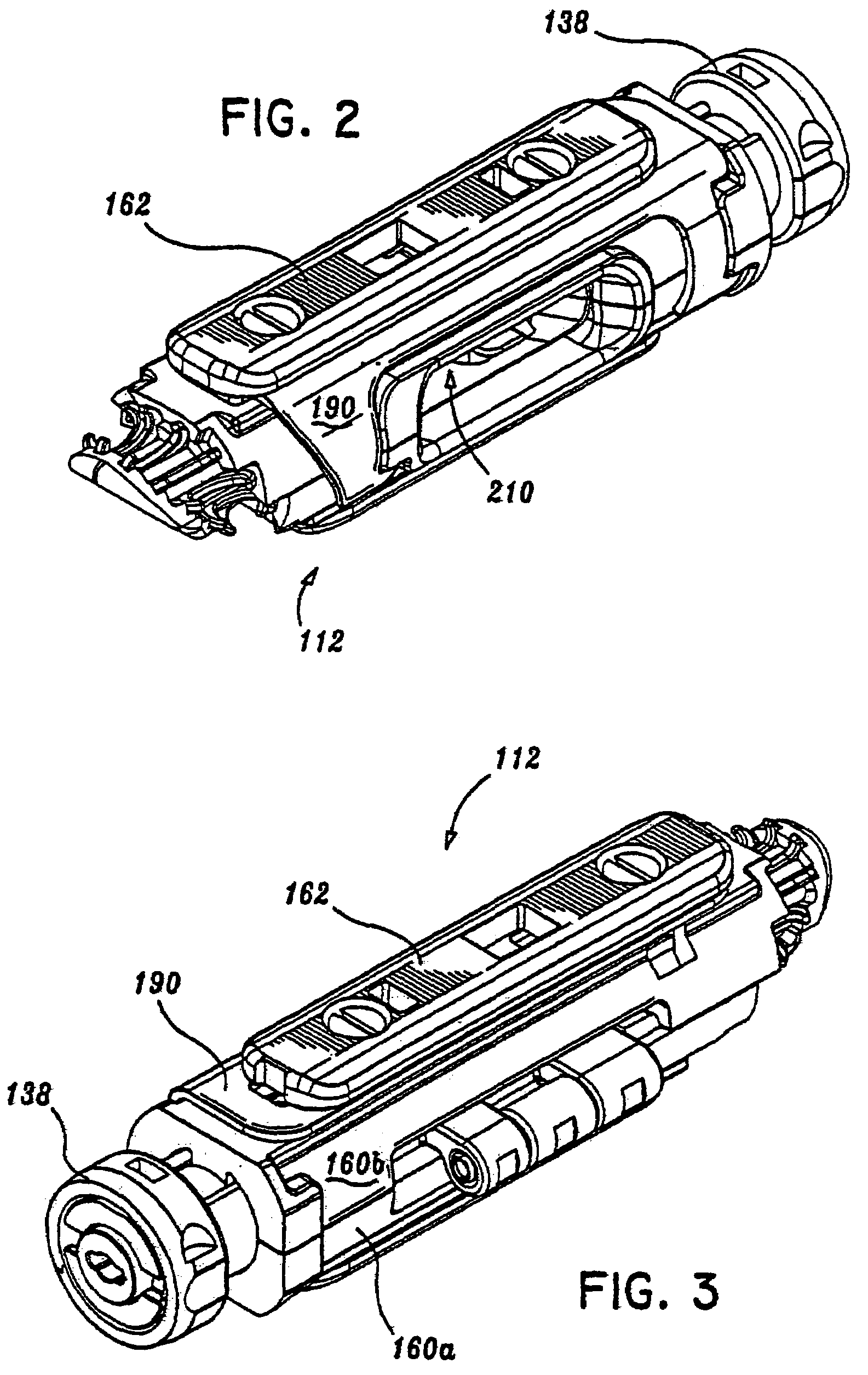
[0066]Referring now in detail to the drawing figures in which like reference numerals identify sim...


PUM


Abstract

A surgical instrument for performing an anastomosis includes a housing having proximal and distal ends and a shaft extending from the distal end of the housing. The instrument also includes an actuator attached to the housing and a disposable loading unit configured for selective attachment to the shaft. The disposable loading unit includes a fastener support member configured and dimensioned to support an array of surgical fasteners thereon and a fastener pusher member which is movable through a firing stroke in response to movement of the actuator to deform the surgical fasteners.

Description

IN THE CROSS REFERENCE TO RELATED APPLICATION[0001]This application is a continuation of U.S. application Ser. No. 10 / 191,599 filed on Jul. 8, 2002 now U.S. Pat. No. 6,726,697 by Nicholas et al. which is a continuation of U.S. patent application Ser. No. 09 / 875,411, now U.S. Pat. No. 6,440,146, filed on Jun. 6, 2001 by Nicholas et al. which is a continuation of U.S. application Ser. No. 09 / 584,541, now U.S. Pat. No. 6,391,039, filed on Jun. 1, 2000 by Nicholas et al. which is a continuation of U.S. patent application Ser. No. 09 / 256,260, now U.S. Pat. No. 6,083,234, filed on Feb. 23, 1999 by Nicholas et al. which is a continuation-in-part of U.S. application Ser. No. 08 / 877,701 now U.S. Pat. No. 6,024,748 filed Jun. 17, 1997 by Manzo et al., which application is a continuation-in-part of U.S. application Ser. No. 08 / 685,385 filed Jul. 23, 1996 by Hinchliffe et al., now U.S. Pat. No. 5,707,380 which claims priority from U.S. Provisional Application Ser. No. 60 / 102,326 which was filed...

Claims


Application Information

Patent Timeline
IPC IPC(8): A61B17/08A61B17/11A61B17/115A61B17/122A61B17/128
CPCA61B17/11A61B17/1152A61B17/1285A61B17/08A61B17/083A61B17/122A61B2017/1107A61B2017/1135
Inventor NICHOLAS, DAVID A.SMITH, ROBERT C.MANZO, SCOTT E.
Owner UNITED STATES SURGICAL CORP
Why Eureka
Try Eureka